How to build a Self-hosted environment on Linux with Proxmox
On this page
- 1. Introduction
- 1.1. Starting point
- 2. Network design
- 3. Building a Network Infrastructure
- 3.1. Downloading and Installing pfSense
- 3.3 Firewall Configuration in pfSense
- 3.4. pfSense Services
- 4.1. Minimum Hardware Requirements
- 4.2. Obtaining the Proxmox Installation Image
- 4.3. Preparing Installation Media
- 4.4. Proxmox VE Installation Process
- 4.5. Proxmox Configuration Procedure
- 4.6. Proxmox Backups
- 5. Internet-exposed Services
- 5.1. Routing traffic
- 5.2. Installing ISPConfig
- 5.2.3. Perfect Server Automated ISPConfig 3 Installation
- 5.3. Websites and mail domains
- 6. Internal Services
- 6.1. Samba Domain Controller
- 6.2. Fileserver
- 7. Managing Users and Computers
- 7.1. Administrative Windows VM
- 8. File sharing
- 9. Connectiong workstations
- 9.1. Overviews
- 9.2. Firewall Rules
- 10. Conclusion
Hi there! I'll start this article with a short personal story.
My journey into the world of IT began in 1999. At the age of almost 21, fresh out of school, I found myself standing at a crossroads. My studies in management, economics, and law no longer sparked my intrinsic interest, but the allure of IT had captivated me. From my early years spent tinkering with C64 home computers, IBM XT (clones), and any device sporting a keyboard, I knew I had found my passion.
Over the years, my skills evolved through self-teaching. I progressed from an installation engineer to the multifaceted role of a network- and system administrator, learning everything through the inherent trials and errors of the process.
A pivotal moment in my journey unfolded during my first assignment for an insurance company. Contemplating the best approach, I decided to set up the client's network at home in my attic office. Successfully configuring the server and workstations, the outcome was satisfying; I implemented the solution on-site in a single attempt.
Not surprisingly, my approach has remained largely unchanged over the years. I immerse myself in understanding an organization's objectives, aligning them with the most fitting IT solutions. Crafting proposals, gaining managerial approval, constructing the IT infrastructure, and finally, project delivery—this methodology has stood the test of time.
My journey has been shaped not only by hands-on experience but also by the invaluable support I derived from books, documentation, and primarily the internet. Above all, it is the open-source communities that have helped me on my journey, fueling my desire to give back. In this spirit, I've chosen to document the foundational elements of network setup, hoping this article proves beneficial for the solitary individual seeking assistance to start their own IT journey. I aim for it to be a source of inspiration and practical insights for those who read this article.
If there are any questions, please feel free to comment or to open a thread on the HowtoForge.com forum. Regards, Bouke
1. Introduction
In this article, we delve into the practicalities of establishing an affordable self-hosted environment tailored for home labs, home offices, and small to medium-sized enterprises. Prioritizing a 'lean' approach that minimizes both effort and cost, our goal is to navigate complexities within a reasonable timeframe.
Drawing on years of hands-on experience within Small and Medium-sized Enterprises (SMEs), we emphasize the integration of open-source solutions whenever viable. It's crucial to recognize that closed-source alternatives are also explored, with the ultimate decision guided by what aligns best with business requirements, practical experience, and technology preferences.
Despite the author's passion for open-source solutions, we acknowledge that instances may arise where a closed-source solution proves more optimal. The underlying message emphasizes the importance of prioritizing company interests over personal preferences, reinforcing the need to align technological decisions with broader business needs.
Self-hosted environments, akin to traditional on-premise setups, are often associated with high initial costs. While hybrid on-premise configurations exist, the self-hosted approach, leaning towards a hybrid setup, can offer cost-effectiveness.
Furthermore, we'll briefly consider alternatives such as migrating to SaaS providers like Microsoft and Google, carefully weighing the associated benefits and costs. Whether opting for a fully independent self-hosted solution or a hybrid form, it provides freedom and control, demanding thoughtful consideration of factors such as security, maintenance, and backups.
1.1. Starting point
Now, let's dig into the nuts and bolts of our self-hosted environment. We need to design an IT environment. The idea is to make sure our IT setup aligns with business goals and supports needs effectively. To get this right, we need to understand the ins and outs of the organization.
When introducing solutions, it's crucial to go beyond technical specs and business requirements. We must also take into account the preferences and needs of the people within our organization. Striking the right balance is key, as achieving user acceptance of solutions is both important and challenging.
In the upcoming sections, we will delve deeper into the specifics of designing our self-hosted environment. We're talking cost-effective solutions, streamlined implementation, and a keen eye on what our organization truly needs. Let's start designing a budget-friendly and effective IT environment!
1.1.1. Network design and internet connnectivity
Our design begins with the backbone of our setup – the network. This encompasses everything from our internet connection and firewall/router to the physical switches and their configurations, including the setup of VLANs. We are diving into the essential elements that keep our self-hosted environment connected and secure. Let's break down each component to ensure a robust and efficient network design in chapter 2.
1.1.2. Routing
Moving on, let's look at a crucial aspect – routing to and from the Internet. This involves delving into the complexitities of one or more fixed IPv4 addresses, along with the discussion of pointer records. We explore various options, such as (routed) subnets, which could be provided by the ISP or established separately via GRE. We will also look into forwarding traffic using iptables under Linux.
In the face of challenges, like limited internet connections where the ISP might not provide multiple IPv4 addresses or set the desired DNS pointer record, we'll explore workarounds. There can even arrise challanges where we are not able to establish a GRE tunnel. We might need to look into alternatives like opting for a fixed IPv4 address through one of the available VPN providers. Let's navigate through these routing considerations to ensure our self-hosted environment efficiently communicates with the broader digital landscape.
1.1.3. Network segmentation
Shifting our focus, let's delve into the crucial realm of network segmentation and highlight the significance of a DMZ (Demilitarized Zone). Essentially, think of a DMZ as a specialized VLAN, but one that plays a pivotal role in managing ingress (and egress) traffic and fortifying our security measures.
Network segmentation matters!
Network segmentation involves dividing our network into distinct segments or VLANs, each serving a specific purpose. This practice isn't just about organization; it's a strategic move to enhance security, efficiency, and overall network performance.
Special note about DMZ
Now, let's zoom in on the DMZ – a VLAN with a unique mission. This zone acts as a buffer between our internal network and the external world, adding an extra layer of defense. It's the go-to place for services that need public accessibility, such as web and mail servers. By isolating these services, we mitigate potential risks associated with direct exposure to our internal network.
As we venture into the complexities of network segmentation and the pivotal role of the DMZ, we're not just creating structure; we're reinforcing the security posture of our self-hosted environment. Let's explore how this strategic design can effectively safeguard our digital landscape (in chapter 2).
1.1.4. Physical server versus hypervisor (VMs)
We'll also need to invite a server to our party. A single physical server with just one operating system can be inefficient and lacks the flexibility needed for dynamic IT environments. In this article, we will work under the assumption of a server equipped with a hypervisor, and a popular choice for this role is Proxmox.
A hypervisor empowers us to create and seamlessly manage multiple virtual machines on a single physical server. Proxmox, in particular, stands out as a powerful open-source hypervisor, optimizing resource utilization and enabling the harmonious coexistence of independent operating systems. In essence, it's a game-changer for efficiency and flexibility in our server infrastructure.
1.1.5. Humble beginnings
In our journey, we kick off with humble beginnings, anchored by a trusty computer affectionately named Scrappy. Scrappy, our dedicated 19" node, boasts an Intel i3-4170 CPU, 24GB of RAM, a 500GB M.2 SSD, and 3x 500GB 2.5" SATA SSDs. This modest 'hardware powerhouse' will take on the role of the Proxmox hypervisor for our virtual machines. This humble server is used to demonstrate that a server environment is not just dependent on raw power.
On the networking front, we opt for open-source robustness, employing the versatile pfSense software for routing and firewalling. It's worth noting that the same results can be achieved with OPNsense. Our VLAN configurations on physical switches are influenced by the design of an HP ProCurve switch. In addition to repurposing an HP switch, one may explore other budget-friendly alternatives such as switches from ZyXEL or TP-Link. In the latter case, TP-Link Omada emerges as a commendable choice, especially when centrally managed with the Omada Controller. You can acquire the Omada Controller as a hardware controller (OC200 or OC300). Alternatively, the Omada software is available in the form of software packages that can be installed on platforms like a Linux VM.
These hardware choices form the backbone of our self-hosted environment, showcasing that even with modest beginnings, we can build a robust and flexible IT infrastructure.
2. Network design
Now that we've wrapped up the introduction, it's time to commence the dynamic journey of network design!
2.1. VLANs and subnets
Before proceeding with a network design, we have to know what "lives" in "our" network? There maybe servers, storage, workstations, printers, guest equipment (mobile phones, tablets or even TVs), solar panel inverters, and of course switches and access points. As soon as an inventory has been made, the nodes can be classified. The idea is to use logical VLANs and subnets for the layout.
Based on an inventariation, the layout could look like this.
| VLAN | Description | Subnet | Explanation (by example) |
|---|---|---|---|
| 0001 | Management 1 | 172.21.1.0/24 | Switches, access points |
| 0002 | Management 2 | 172.22.2.0/24 | Hypervisor(s), KVM-over-IP (eg iLO, IPMI) |
| 0016 | Servers | 10.10.16.0/24 | Server VMs |
| 0018 | Storage | 10.10.18.0/24 | Network Attached Storage (NAS) |
| 0032 | Office LAN | 10.10.32.0/24 | Workstations (desktop and laptop computers) |
| 0036 | Peripherals | 10.10.36.0/24 | Printers |
| 0251 | IoT | 172.31.251.0/24 | Solar panel inverters |
| 0252 | DMZ | 172.31.252.0/24 | Web and mail server |
| 0253 | GuestNET | 172.31.253.0/24 | Guest Wi-Fi network |
2.1.1. VLANs
In this network design, the primary distinction lies in separating critical components, including network equipment, hypervisor(s), server VMs, peripheral devices (such as printers), workstations, and internet-facing services.
In the context of one or more Remote Desktop Servers (formerly known as Terminal Servers), it becomes evident that establishing a distinct VLAN is crucial. This decision stems from the consideration of classifying a Remote Desktop Server not merely as a traditional server but rather as a specialized workstation. While it functions as a server, placing it directly within the Office LAN may not be the most suitable approach, emphasizing the need for a separate VLAN.
Furthermore, the strategic placement of domain controllers warrants careful consideration. Placing a domain controller within the general server VLAN can potentially expose it to security vulnerabilities. To enhance security measures, it is advisable to allocate a dedicated VLAN for domain controllers. This approach minimizes the attack surface by only opening the most essential ports, contributing to a more robust and secure network infrastructure.
For added security, the concept of creating distinct VLANs for writable domain controllers and read-only domain controllers can be explored. This segmentation ensures that exposure to other servers and clients is meticulously controlled, fortifying the overall security posture of the network.
Understanding the rationale behind VLAN numbers and subnets is crucial. While it's practical to keep the management VLANs grouped together, the subnets are deliberately varied. For the management VLANs, identifying the VLAN is intuitive; one can determine their VLAN location by observing the third (and also the second) octet, indicating management VLAN 1 or management VLAN 2.
This same logical approach extends to the third octet across other VLANs, providing a systematic and easily interpretable structure throughout the network.
2.1.2 Subnets
In the preceding paragraph, we briefly touched upon subnets.
It is okay if this paragraph is not fully understood immediately. Just use the IP calculator recommended below and revisit the theory later if necessary. Understanding the jist of this subject is good enough and using an IP calculator and common sense is sufficient to succeed!
Subnets necessitate thoughtful calculation and logical design, each defining a specific IP range. For instance, the Office LAN spans from 10.10.32.0 to 10.10.32.255, accommodating up to 254 hosts with a CIDR mask of /24 (equivalent to a subnet mask of 255.255.255.0), establishing a structured subnet. To accommodate potential growth, consider expanding the IP range to 10.10.32.0 - 10.10.35.255 with a CIDR mask of /22 (translating to a subnet mask of 255.255.252.0), ensuring adaptability to evolving organizational needs.
Understanding how to calculate subnets is crucial for network design. The process involves determining the size of each subnet, which is essential for IP address management.
Formula
The formula to calculate subnet size is: Subnet Size = 2^(32 - CIDR). Here, CIDR (Classless Inter-Domain Routing) represents the notation used to specify the size of a subnet.
For example, if you have a CIDR notation of /24, the calculation would be: Subnet Size = 2^(32 - 24) = 2^8 = 256 addresses. This means the subnet can accommodate 256 hosts.
We need to take the follwing into account: host addresses: 256 - 2 = 254 hosts
- The subtraction of 2 accounts for the network address and the broadcast address!
So, when we say a /24 subnet accommodates 254 hosts, it's a simplified way of expressing that 256 addresses are available, but two are reserved for network and broadcast addresses. This can be initially confusing for those new to networking, but it's a standard practice in IP addressing.
Another variable to take into account is that counting starts at "zero": 0-255 means 256.
To explore other possibilities...
- Recalculation for /23: Subnet Size = 2^(32 - 23) = 2^9 = 512 addresses.
- Recalculation for /22: Subnet Size = 2^(32 - 22) = 2^10 = 1024 addresses.
- Recalculation for /21: Subnet Size = 2^(32 - 21) = 2^11 = 2048 addresses.
Additionally, considering a smaller CIDR notation like /29: Subnet Size = 2^(32 - 29) = 2^3 = 8 addresses. This implies the subnet can accommodate 8 hosts.
Regarding CIDR /29, it's important to note that a minimum of two IPs is unusable due to the network and broadcast address. Additionally, one IP is reserved for the router, leaving room for a practical total of five usable nodes.
Note that as the CIDR value decreases, the subnet size increases, providing more host addresses but potentially requiring more IP addresses from the overall network space. An IP calculator, such as the one available at jodies.de, can expedite these calculations for efficient network planning.
The latter is important when looking at DMZ. One might argue to keep the subnets for several DMZs as small as possible for enhanced security. A sensible approach to further enhanced security by logically separating different services within distinct DMZs. It adds a layer of isolation, minimizing potential risks and containing any security breaches to specific segments.
A note on binary calculation
Behind the scenes, subnet calculations involve binary operations. Let's break down the example of a /24 CIDR notation:
CIDR Notation: /24
Binary Representation: 11111111.11111111.11111111.00000000
The series of 1s in the binary representation signifies the network portion, while the series of 0s represents the available host addresses. The subnet size is determined by counting the number of zeros. In a /24 subnet, there are 8 zeros, translating to 2^8, which equals 256 addresses.
Understanding this binary aspect provides insight into the foundational mechanics of subnetting. While not essential for everyday calculations, it offers a deeper comprehension of how CIDR notation influences subnet size in the realm of binary digits (bits). If readers wish to delve into the binary nuances, this knowledge can enhance their understanding of networking principles.
Like the IP calculator metioned, the use of a subnet cheat sheet can help. Please take a look at the IPv4 Subnetting cheat sheet [PDF] of Jeremy Strectch's populair website packetlife.net!
2.1.3 Unraveling VLANs
Continueing on our exploration of VLANs, we delve into the realm of VLAN configuration. VLANs, or Virtual Local Area Networks, serve as pivotal tools for logically segmenting networks, enhancing both organization and security. To navigate the complexity of VLANs effectively, a foundational understanding of key concepts, including VLAN trunking, is important.
It is okay if this paragraph is not fully understood immediately. In the following chapter we will put the theory into practice! Understanding the jist of this subject is good enough.
Ultimately, it's practice that makes perfect! It is normal that you do not immediately grasp how to apply the theory in practice. More explanation with practical examples will follow in the following chapters.
Understanding IEEE 802.1Q
VLANs operate within the framework of the IEEE 802.1Q standard, a protocol designed to seamlessly embed VLAN information into Ethernet frames. This tagging mechanism empowers switches and routers to discern the VLAN membership of each packet, ensuring the precise routing and forwarding of traffic within the network.
Tagged vs. Untagged VLANs
Tagged VLANs:
In a tagged VLAN setup, each Ethernet frame carries additional information in the form of tags, clearly indicating its VLAN membership. This method proves indispensable between switches and routers, enabling devices to identify and process traffic from diverse VLANs.
Untagged VLANs:
Conversely, untagged VLANs omit additional information in Ethernet frames. This configuration finds application when linking end devices - such as workstations or printers - to a switch port associated with a specific VLAN.
VLAN Trunking
VLAN trunking emerges as a critical concept, particularly in scenarios where multiple VLANs traverse the same physical link. Trunks, specialized network links, are configured to adeptly convey traffic for multiple VLANs, fostering efficient communication between switches and routers.
Configuration Overview
Router/Firewall Configuration:
VLANs necessitate configuration on the router/firewall to facilitate inter-VLAN communication. Each VLAN receives an assigned IP subnet, accompanied by established routing rules governing traffic flow between VLANs.
Switch Configuration:
Switch ports linked to devices within a VLAN can be designated as either tagged or untagged. In contrast, trunk ports are configured to transport tagged frames for multiple VLANs, enhancing the network's flexibility and scalability.
Hypervisor Configuration:
In the virtualization landscape, hypervisors must be aware of VLAN configurations, especially when overseeing multiple virtual machines. Virtual network interfaces are allocated to specific VLANs, mirroring the tagging principles observed in physical networks.
By unraveling the complexities of IEEE 802.1Q, delving into the nuances between tagged and untagged VLANs, and comprehending the significance of VLAN trunking, we lay a robust foundation for crafting a well-organized and secure network infrastructure. This foundational knowledge sets the stage for the subsequent configuration steps in our comprehensive network design journey.
2.1.4. Routing
In our exploration of network design, routing takes center stage, presenting two distinctive strategies: the "router-on-a-stick" method and layer-3 routing. Additionally, we adopt a firewall-centric approach, orchestrating traffic flow between VLANs through firewall rules.
Router-on-a-Stick vs. Layer-3 Routing
2.1.4.1. Router-on-a-Stick
This strategy involves a single physical interface on a router, serving multiple VLANs. The router processes inter-VLAN traffic, making routing decisions based on internal VLAN tags. While practical, it may introduce a potential bottleneck, as all traffic converges on a single link.
2.1.4.2. Layer-3 Routing
Here, layer-3 switches handle inter-VLAN routing. Each VLAN has a dedicated layer-3 interface, promoting parallel processing of traffic. This minimizes bottlenecks and enhances overall network efficiency.
2.1.4.3. Firewall-Centric Approach
Our network design emphasizes a firewall-centric approach. Firewall rules meticulously govern traffic between VLANs, ensuring that all data traverses through the firewall. This not only offers granular control over communication but also enhances security by scrutinizing and filtering traffic at the network's edge.
In the subsequent sections, we'll delve into the configuration, illustrating how these routing strategies and firewall-centric principles synergize to fortify our network's structure and security posture.
3. Building a Network Infrastructure
In this exciting phase, we roll up our sleeves and initiate the actual construction of our network.
Initiating the Network Build
We're at the point where theory transforms into tangible infrastructure. This marks the beginning of assembling the elements that will form the backbone of our network.
- 3.1. Downloading and Installing pfSense
Our first order of business involves the deployment of pfSense, a robust open-source software for routing and firewalling. We'll guide you through the download and installation process, ensuring a seamless setup. - 3.2. Basic pfSense Setup and VLAN Integration
With pfSense in place, we move on to the foundational setup. This includes configuring pfSense with the essential details and integrating Virtual Local Area Networks (VLANs). Additionally, we'll implement crucial firewall rules to regulate traffic flow between VLANs, bolstering security measures. - 3.3. Switch Configuration and VLAN Deployment
Now, attention turns to the switches. We'll delve into setting up VLANs on the switches, aligning them with our predetermined network structure. This pivotal step ensures that the logical segmentation defined by VLANs is seamlessly extended across the entire network.
By progressing through these steps, you're laying the groundwork for a resilient, secure, and well-organized network. As each component falls into place, the intricate design conceived in the theoretical chapters takes tangible form. Get ready to witness your network blueprint come to life!
3.1. Downloading and Installing pfSense
We will dowload and install pfSense.
3.1.1. Minimum Hardware Requirements
When contemplating the question of minimum hardware requirements, rest assured that the pfSense software firewall distribution operates efficiently with modest hardware. For precise details, refer to the dedicated page: pfSense Minimum Requirements. However, what's truly crucial is the Hardware Sizing Guidance, providing insights into the hardware prerequisites tailored to achieve your desired throughput.
Throughout this chapter, we will be using a PC Engines APU3 featuring an AMD GX-412TC CPU and 4GB RAM. The storage is a single 250GB M.2 SSD. While a 16GB M.2 SSD is typically used, this APU has previously functioned as a Linux node running Debian.
It's worth noting that APU boards come without a video connector, necessitating interfacing via a serial connection. This unique characteristic makes this board ideal for demonstrating the installation process.
3.1.2. Obtaining the pfSense Installation Image
To acquire the pfSense Installation Image, visit the official download location: pfSense Download Page.
The download page provides a user-friendly interface for selecting and downloading the appropriate image. Choose the desired options based on architecture (AMD64 - 64-bit; Netgate ADI), installer type (USB Memstick Installer; DVD Image (ISO) Installer), console preference (Serial; VGA), and select a mirror for download.
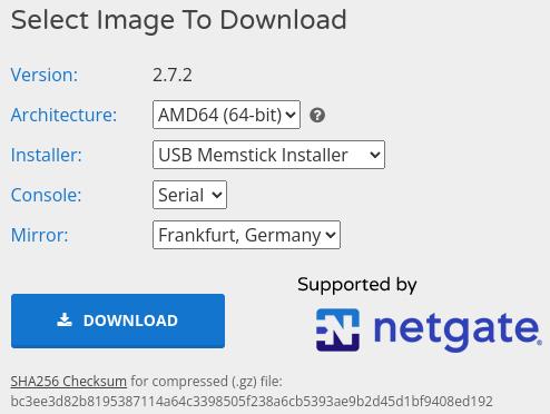
For the APU system board, it's recommended to opt for the AMD64 (64-bit) USB Memstick Installer configured for a Serial console. However, if the hardware features a video card, the VGA option is preferable for a more conventional setup.
3.1.3. Preparing Installation Media
Before you kick off the installation process, ensuring your installation media is ready becomes a crucial step.
3.1.3.1. Decompress Gzip image
The pfSense installation image arrives compressed with Gzip, and here's how you can decompress it depending on your operating system.
For Linux or Mac:
Use the command `gzip -d` or `gunzip` in the terminal.
gzip -d pfSense-CE-memstick-serial-2.7.2-RELEASE-amd64.img.gz
Windows:
For Windows users, tools like 7-Zip are ideal as they support GZip compression. Simply use 7-Zip to decompress the installation image.
3.1.3.2. Write image to USB Memstick
Once decompressed, you'll need to write the image to a USB Memstick for installation on the target system. This crucial step ensures that your installation media is ready and sets the stage for a smooth installation process.
Write the installation image to USB Memstick
3.1.3.2.1. Write image with Linux
Here is how to install the image to a USB Memstick with a Linux computer.
1. Open a terminal (eg `xterm` or `xfce4-terminal`)
2. Become root by executing `sudo su` or `su -u`in the terminal.
sudo su
3. Navigate to the Downloads directory, create a folder (pfSense), move the image to the folder, cd into the folder
cd Downloads/
mkdir pfSense
mv pfSense-CE-memstick-serial-2.7.2-RELEASE-amd64.img.gz pfSense/.
cd pfSense/
4. Decompress the image
gzip -d pfSense-CE-memstick-serial-2.7.2-RELEASE-amd64.img.gz
Verifty the result with the `ls` command.
ls -lahsi
Next, you need to identify the correct device name for your USB Memstick, which, in this example, is /dev/sdb.
fdisk -l
The output will resemble something like the following.
[..]
Disk /dev/sdb: 7,2 GiB, 7736072192 bytes, 15109516 sectors
Disk model: DataTraveler 3.0
Units: sectors of 1 * 512 = 512 bytes
Sector size (logical/physical): 512 bytes / 512 bytes
I/O size (minimum/optimal): 512 bytes / 512 bytes
Disklabel type: dos
Disk identifier: 0x90909090

Device Boot Start End Sectors Size Id Type
/dev/sdb1 1 66584 66584 32,5M ef EFI (FAT-12/16/32)
/dev/sdb2 * 66585 2047848 1981264 967,4M a5 FreeBSD
/dev/sdb3 2047849 2178920 131072 64M b W95 FAT32
Finally, use the `dd` command to write the image to the USB Memstick (replace "sdX" with your specific device name).
Caution regarding the `dd` command! Exercise extreme care to avoid inadvertently selecting the wrong device when overwriting. This mishap could result in significant data loss or render your computer unbootable. Always double-check and confirm the target device before executing the `dd` command. Your diligence in this step is crucial to prevent any unintended consequences.
dd if=pfSense-CE-memstick-serial-2.7.2-RELEASE-amd64.img of=/dev/sdX status=progress ;sync
The `dd` command may take some time to finish, so be patient. Once completed, your USB Memstick will be ready for the pfSense installation process.
The output will resemble something like the following.
40735232 bytes (41 MB, 39 MiB) copied, 5 s, 8,1 MB/s
[..]
1112005120 bytes (1,1 GB, 1,0 GiB) copied, 257 s, 4,3 MB/s
2178921+0 records in
2178921+0 records out
1115607552 bytes (1,1 GB, 1,0 GiB) copied, 273,834 s, 4,1 MB/s
3.1.3.2.2. Write image with Windows
The process on a Windows computer differs from that on a Linux system.
Win32 Disk Imager is one of the documented tools in the Netgate Docs, and you can find a detailed description of th procedure under Writing an Installation Image to Flash Media in the Netgate Docs.
3.1.3.3. pfSense Installation Process
Now, let's move on to the installation process (because it is time to boot and te become root)! Go ahead and plug in the USB Memstick into the computer that's about to take on the roll of the firewall. Before turning on the computer, it's advisable to identify the key to press for accessing the boot menu. This step is crucial to be able to boot from the USB Memstick.
In the case of the APU, which lacks a video connection, it must be operated via a serial console connection. On Linux, the screen command can be used. Alternatively, you can use PuTTY, available on various platforms. For simplicity, we'll use PuTTY to walk you through the process. This approach works similarly whether you have a video card or not, with just a few nuances in the display.
The serial console installation was chosen purposely in the hope of removing the barrier for this type of installation. By demonstrating the procedure, you will notice that it is not complicated. The disadvantage is that a suitable serial cable is required. PC Engines has a simple solution for this in the form of a USB to DB9F cable. PC Engines even provides a schematic [PDF] and drivers.
The laptop chosen for this demonstration lacks a serial port. Let's introduce a Tripp Lite Keyspan USB to Serial Adapter (USA-19H). This handy adapter bridges the gap, enabling a smooth serial connection for our installation process. Now, let's add this tech superhero to the mix and proceed with the installation magic!
To connect to the APU using the `screen` command on Linux, you'd execute `screen /dev/ttyUSB0 115200`. However, for this demonstration, we'll opt for PuTTY.
The significance of `/dev/ttyUSB0` lies in it being the device name on the Linux laptop. In Windows, you can navigate to Device Management t to locate the serial device. Instead of `/dev/ttyUSB0`, the device name might appear as something like `COM3:`. In both cases, establishing a connection to the APU is vital.
Alongside the port, knowing the speed is crucial. The speed, in this case, is set to 115200 baud. Let's seamlessly blend these components into our installation journey!
- Open a terminal.
- Become root (`sudo su` or `su -`)
- Connect the USB serial adapter to the computer and the APU.
- Plugin the USB Memstick.
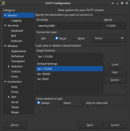
- Start PuTTY
- Set the connection type to serial, put the device name in the text box Serial Line and finaly set the Speed to 115200.

- Click the [Open] button.
- Switch on the APU by plugging in the power cable.
- Press <F10> during boot (just spam the <F10> key, until the boot menu appears)
- Select the boot device (enter the corosponding number)
The following represents the boot menu. The first option is the USB Memstick. The second option is the 250GB M.2 SATA SSD.
SeaBIOS (version rel-1.16.0.1-0-g77603a32)
Press F10 key now for boot menu
Select boot device:
1. USB MSC Drive Kingston DataTraveler 3.0
2. AHCI/0: Samsung SSD 850 EVO mSATA 250GB ATA-9 Hard-Disk (232 GiBytes)
3. Payload [setup]
4. Payload [memtest]
If your hardware includes a video card, the VGA option is more convenient. Simply plug in the USB Memstick, switch on the computer, and start spamming the boot key. The rest of the process is similar, with only a few nuances in the display.
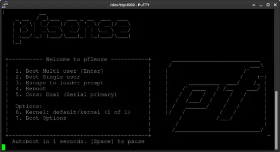
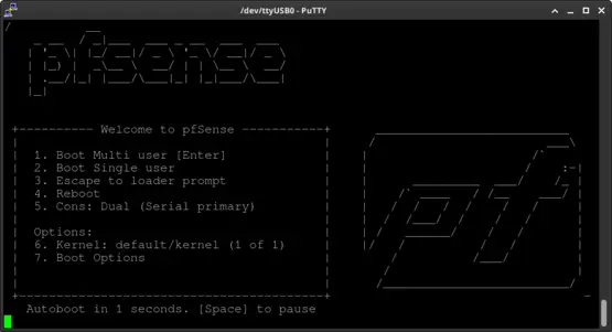
pfSense will autoboot.
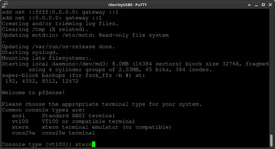
Select the console type. Type "xterm" and press Enter to continue.
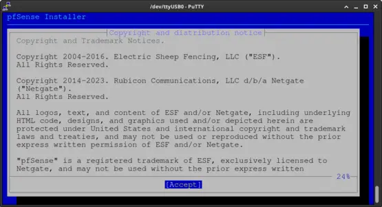
Proceed to the next step by accepting the copyright and distribution notice. Press Enter to continue.
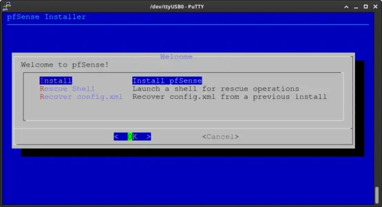
Press Enter at the Welcome screen to initiate the installation process.
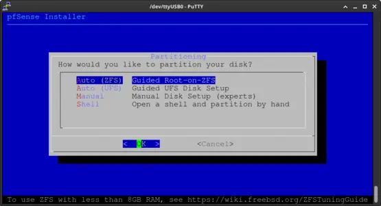
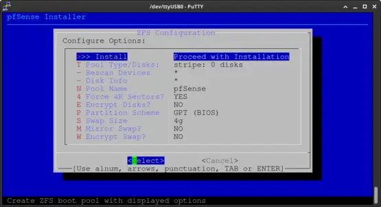
Press the Enter key to choose Auto (ZFS). If you are utilizing eMMC (or a similar option), select Auto (UFS).
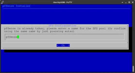
Simply press Enter to proceed. The installer will automatically re-partition and overwrite the M.2 SSD.
Press Enter to proceed. Note: consider increasing the Swap Size to address potential RAM exhaustion.
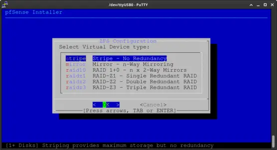
You'll notice only one device. Simply press Enter to confirm the "No Redundancy" option.
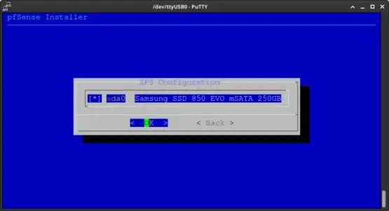
Press the space bar to select the device. Next press Enter to continue.
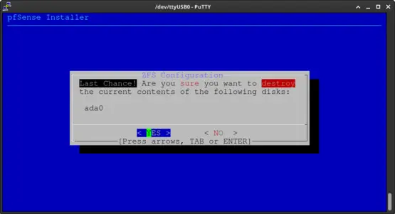
Press the TAB key to select "YES". Next press the Enter key to continue.
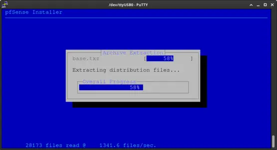
The installer will continue. Please stand by.
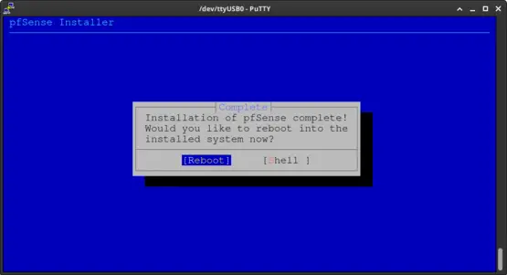
Press Enter to reboot.
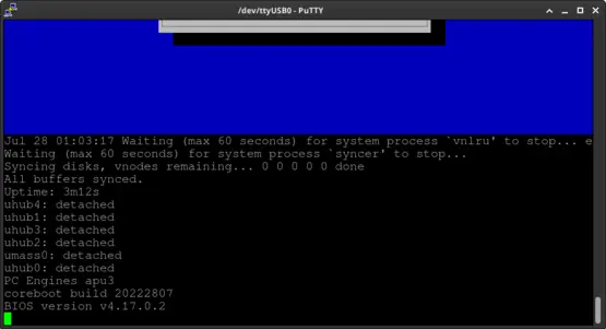
Feel free to remove the USB Memstick once you spot the line "All buffers synced."
Congratulations! pfSense successfully boots from the internal storage. We're now on the brink of configuring pfSense according to our network design.
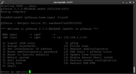
Upon the initial boot, you might be prompted to configure VLANs as well as the WAN and LAN interfaces.
pfSense will display the following information through the console:
- Default interfaces not found --- Running interface assignment option.
[..] - Valid interfaces are:
[..] - Do VLANs need to be set up first?
If VLANs will not be used, or only for optional interfaces, it is typical to say no here and use the WebConfigurator to configure VLANs later, if required.
[..] - Shoud VLANs be setup now [y|n]?
Just type n and press Enter. - [..]
Enter the WAN interface name or 'a' for auto-detction.
Just enter the name of the desired interface for WAN and press ENTER. -
Enter the LAN interface name or 'a' for auto-detction.
Just enter the name of the desired interface for WAN and press ENTER.
- If there are more interfaces, you will be asked to set the Optional 1 interface.
Just press Enter to skip, if this is the case. - The interfaces will be assigend as follows:
[..]
Do you want to proceed [y|n]?
Type y and press Enter.
The end result should look similar to the next screenshot.
3.2. Configuring pfSense
Now that pfSense is successfully installed, we can move on to configuring the router/firewall using the webConfigurator. The webConfigurator is accessible on port 443 and can be reached through the default IPv4 address of the firewall, which is 192.168.1.1.
Please note: different terminologies are used interchangeably for the webConfigurator, such as "WUI," "WebUI," "WebGUI," or simply "Web Interface."
3.2.1. Web Interface
Ensure your computer is connected to the LAN port of the firewall, typically identified as the second network interface. If all is well, an IPv4 address will be assigned to your computer. Now, open a web browser and go to https://192.168.1.1 to open the WebUI.
3.2.1.1. pfSense Setup Wizard
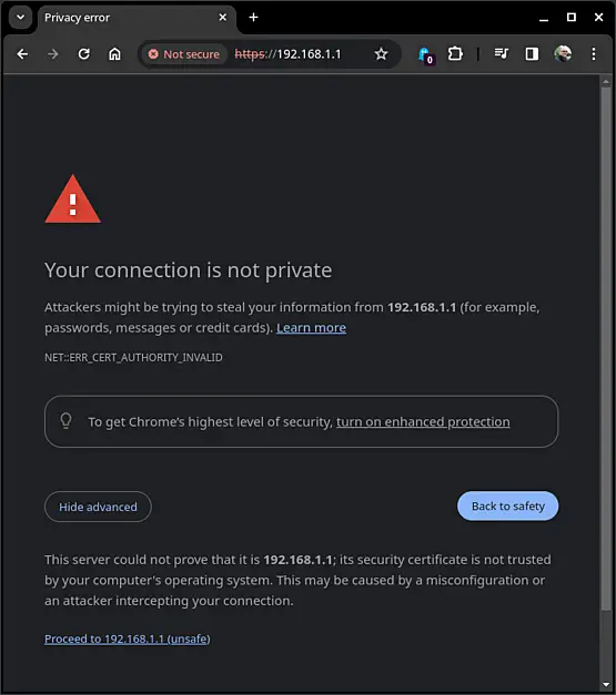
The initial screen might seem a bit cautious, but no worries - just consider it a friendly reminder. Since a self-signed certificate is in use, click on Advanced and then confidently select Proceed to 192.168.1.1 (unsafe) to continue.
For Firefox users, the process is equally smooth. Simply click on Advanced..., and then opt for "Accept the Risk and Continue" to proceed with confidence.
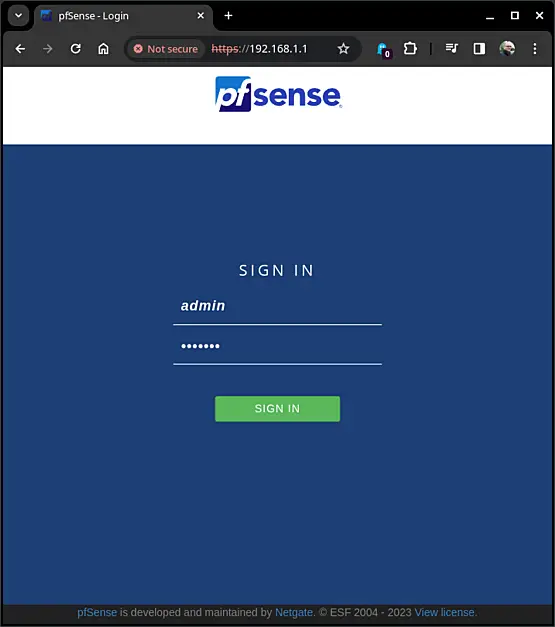
Now, it's time to sign in. Enter "admin" for the username and "pfsense" for the password. Afterward, click on "Sign in" to access the WebUI.
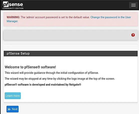
You can safely disregard the warning message about the password for now. Proceed by clicking on "Next" to continue with the pfSense Setup Wizard.
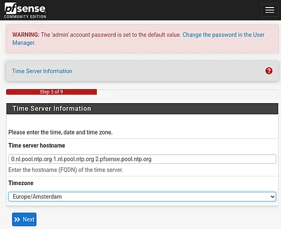
Ensuring accurate time and date settings is crucial. You can either accept the default time source or add more if needed. Then, proceed to set the timezone and click "Next."
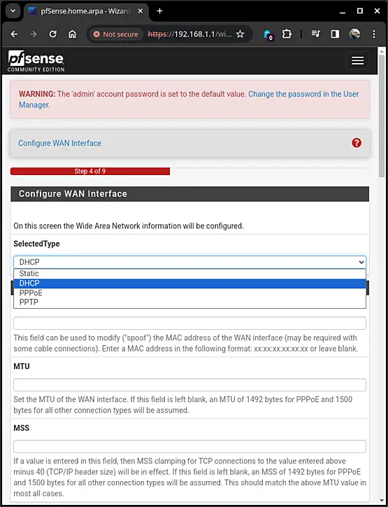
Next on our list is the configuration of the WAN Interface. You'll need to choose from options like Static, DHCP, PPPoE, and PPTP, based on your internet connection or the network to which the firewall is connected. Select the appropriate option accordingly, click on "Next" once it's set.
In this example, we'll select the DHCP option, connecting the firewall to the lab network via one of the switch ports. The lab network, in turn, is linked to another firewall that connects to the internet.
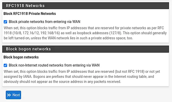
Next, we need to decide how to handle RFC1918 networks and bogons. To maintain security, it's advisable to keep both options checked, ensuring that traffic from these networks is blocked. However, if the WAN interface is connected to an RFC1918 network, you might consider unticking the first box. Once you've made your selection, click on "Next" to proceed.
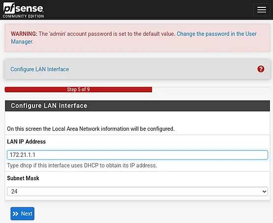
We will enter the default gateway IPv4 "172.21.1.1" of our primary management VLAN, configuring the LAN interface. Set the Subnet Mask to 24, and then click "Next" to proceed.
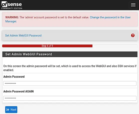
We will be asked to set the password for the WebGUI.Just follow the on-screen instructions.
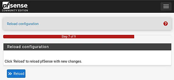
We're almost at the end of the pfSense Setup Wizard. Simply click on "Reload" to apply the new changes and reload pfSense.
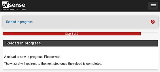
Once the reload is complete, the wizard should automatically redirect. However, in some cases, this redirection may not function as expected.
Upon closer inspection, it appears that the IPv4 address of the network card is not being renewed. This issue is attributed to NetworkManager on the Linux laptop being used, rather than a problem with pfSense.
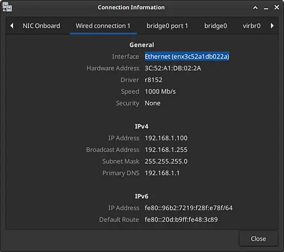
After unplugging the network cable, waiting a few seconds, and re-plugging it back into the laptop, the IPv4 address appears to be successfully renewed.
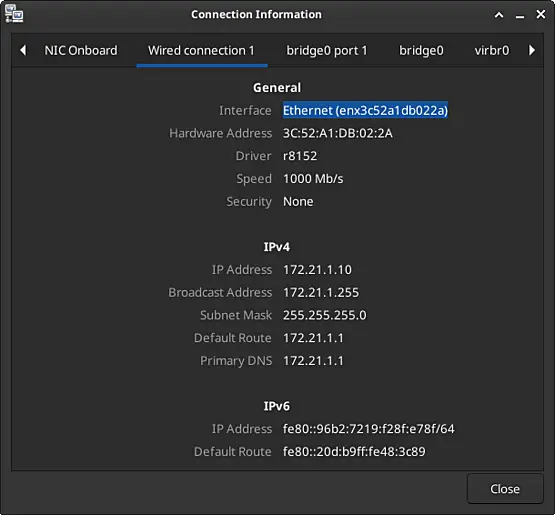
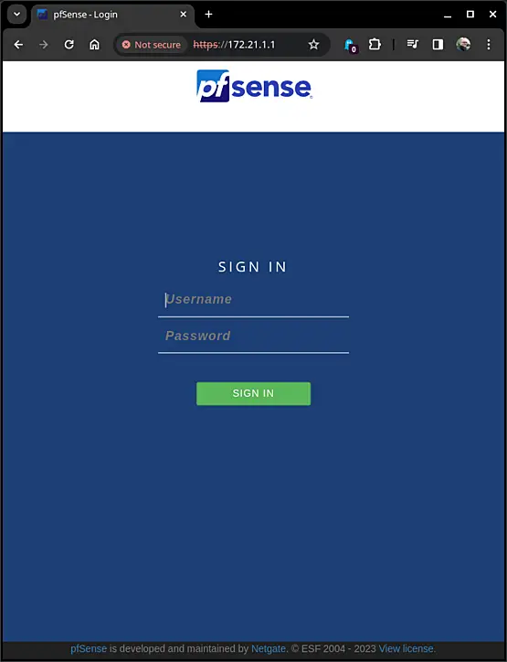
After entering the correct URL "https://172.21.1.1" in the browser's address bar, press the Enter key. Then enter the username "admin" and the previously set password. Finally, click "Sign in" to access the WebUI.
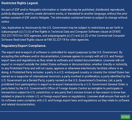
Upon logging in, you'll be greeted with some awesomeness that you simply need to accept. Click on "Accept" and then proceed by clicking "Close."
Congratulations! The pfSense Setup Wizard concludes here. We will proceed with some customizations.
3.2.1.2. customizations
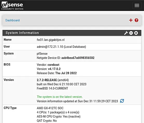
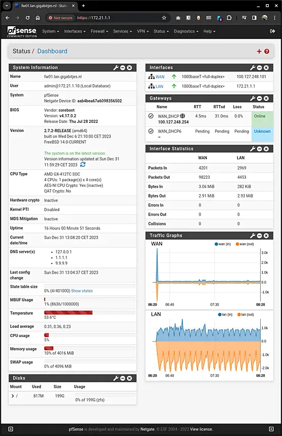
Dashboard
The pfSense dashboard is functional but can be enhanced by adding various widgets. If you prefer, you can remove the Services And Support widget by clicking the 'X' in the top right corner.
Consider adding useful widgets such as "Gateways," "Interface Statistics," and "Traffic Graphs" to enrich your dashboard. While there are more beneficial widgets available, we'll leave it to the admin to explore and decide which ones suit their preferences.
Theme and Top Navigation
Some may prefer to use a dark mode theme. The theme can be selected via the menu option "System" > "General Setup". Scroll down to "webConfigurator" and select the desired theme by scrolling through the available options. Choosing "pfSense-dark" will result in a dark background.
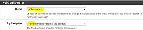
Additionally, pay attention to the "Top Navigation" option. Opting for "Fixed" ensures that the navigation menu remains at the top of the page at all times. Scroll down and click on "Save" to store and apply the changes.
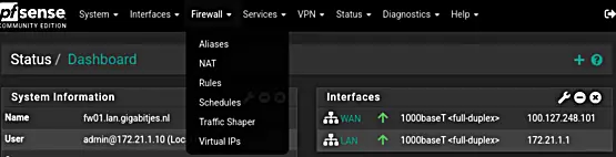
To refresh the Dashboard and appreciate the improved appearance, simply click on the pfSense logo located in the upper left corner. Enjoy the updated interface!
Explore numerous customization options within the pfSense webConfigurator for a personalized experience. Consider enhancing the aesthetics by adding a delightful image using the Picture widgets. Perhaps creativity should be saved for later, because there is work to be done.
Take a moment to explore the menu options; it's a valuable step to become familiar with the navigation. Understanding the menu will prove beneficial as we delve into further configurations.
Let us move on to the next section on VLANs and subnets.
3.2.2. Defining VLANs and Subnets
Recall our network design? We've included an additional column for the default gateway.
In our network design, each network has its own designated default gateway. The default gateway serves as the central point for network traffic to exit and enter, ensuring efficient communication between different networks. This individualized setup enhances network organization and functionality.
| VLAN | Description | Subnet | Gateway | Explanation (by example) |
|---|---|---|---|---|
| 0001 | Management 1 | 172.21.1.0/24 | 172.21.1.1 | Switches, access points |
| 0002 | Management 2 | 172.22.2.0/24 | 172.22.2.1 | Hypervisor(s), KVM-over-IP (eg iLO, IPMI) |
| 0016 | Servers | 10.10.16.0/24 | 10.10.16.1 | Server VMs |
| 0018 | Storage | 10.10.18.0/24 | 10.10.18.1 | Network Attached Storage (NAS) |
| 0032 | Office LAN | 10.10.32.0/24 | 10.10.32.1 | Workstations (desktop and laptop computers) |
| 0036 | Peripherals | 10.10.36.0/24 | 10.10.36.1 | Printers |
| 0251 | IoT | 172.31.251.0/24 | 172.31.251.1 | Solar panel inverters |
| 0252 | DMZ | 172.31.252.0/24 | 172.31.252.1 | Web and mail server |
| 0253 | GuestNET | 172.31.253.0/24 | 172.31.253.1 | Guest Wi-Fi network |
We will use our network design to add the VLANs and subnets.
3.2.2.1. Interfaces
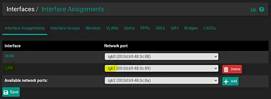
Let's kick things off by selecting the interface for our VLANs. Navigate to "Interfaces" > "Assignment" to view the available interfaces.
The LAN interface is currently associated with igb1. Therefore, we will utilize igb1 for configuring our VLANs.
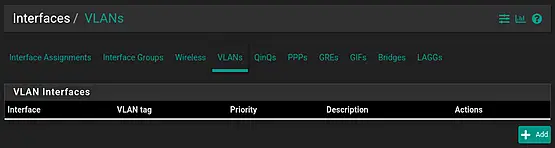
3.2.2.2. VLANs
Select "VLANs" under "Interfaces" > "Assignment", and then click on "Add" to set up the VLAN.
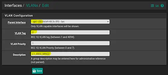
Choose the appropriate parent interface, which in this case is "igb1". Enter the VLAN Tag as "2" and leave the VLAN Priority unset.
Pay careful attention to the Description field, where it's recommended to use a clear format. For example, you can use "L1_0002_MNG2", where "L1" denotes "LAN 1", "0002" signifies the VLAN, and "MNG2" represents "Management LAN 2". This structured approach aids in easily recognizing and managing the network.
Finaly click on "Save" to save the changes.
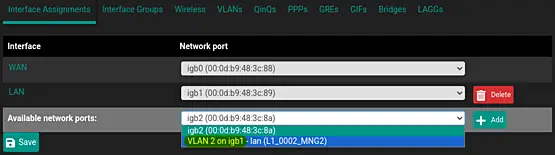
Navigate to "Interface Assignments" under "Interface" > "Assignments" to assign the new VLAN to an interface. In the "Available network ports" section, select the VLAN and click on "Add". Then, save and apply the settings.
Enable the interface by checking the checkbox. Pay careful attention to the Description field, where it's recommended to use a clear format. For example, you can use "L1_0002_MNG2"
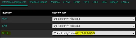
Once the configuration options are visible, proceed with the following steps.
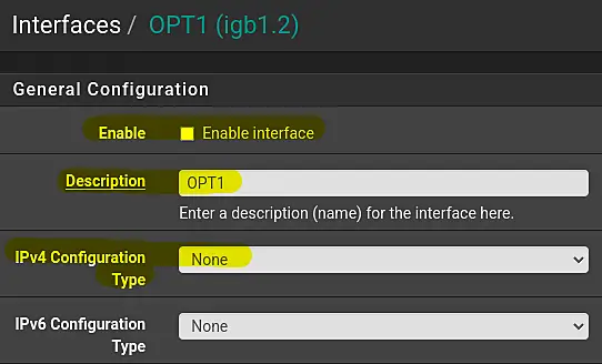
- Enable the interface by checking the checkbox.
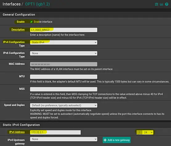
- Pay close attention to the Description field, where it is recommended to use a clear format. For instance, you can use "L1_0002_MNG2".
- Select "Static IPv4" as the "IPv4 Configuration Type".
- Enter the default gateway IPv4 as "172.22.2.1" in the text field next to the label IPv4 Address.
- Choose "24" on the right of the IPv4 address; this represents the subnet mask in CIDR format.
- Finally scroll down, then save and apply the changes.
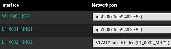
The result will look something like this.
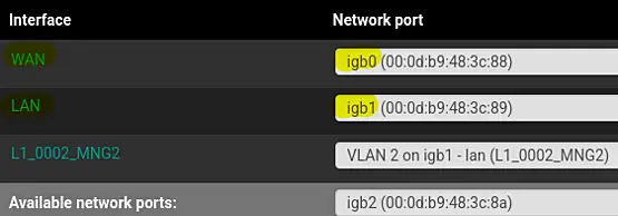
It is good practice to rename the LAN and the WAN interfaces too.
Simply click "LAN" and change the description of the interface to "L1_0001_MNG1".
Next do something similar to the WAN interface by chaning the description to "W1_0001_ISP1".
This will provide a consistent overview.
Do not forget to save and apply every change.
Here's a summary of the process for creating VLANs and interfaces:
-
Create the VLAN:
- Navigate to "Interfaces" > "Assignments."
- Click on the "VLANs" tab.
- Click "Add" to define a new VLAN.
- Select the parent interface (e.g., igb1), enter the VLAN Tag, and provide a clear Description.
-
Express the VLAN in an Interface:
- Go to "Interfaces" > "Assignments."
- Click on "Interface Assignments."
- Choose the VLAN from the "Available network ports" list and click "Add."
- Save and apply the settings.
-
Configure the Interface Options:
- In the "Interfaces" section, a new interface (e.g., OPT2) will appear.
- Click on the interface (e.g., OPT2).
- Enable the interface by checking the checkbox.
- Set a clear Description, such as "L1_00016_SRVS. for servers"
- Choose "Static IPv4" as the "IPv4 Configuration Type."
- Enter the default gateway IPv4 address (eg., 10.10.16.1).
- Choose the subnet mask in CIDR format (e.g., /24).
- Scroll down, then save and apply the changes.
-
Repeat for Other VLANs and Interfaces:
- Repeat the entire process for each VLAN and corresponding interface.
- Be consistent in providing clear Descriptions for better organization.
By following these steps, you can systematically create VLANs, express them in interfaces, and configure the necessary settings. If you have specific VLANs or interfaces you'd like detailed instructions for, feel free to specify!
The VLAN overview will look similar to the following table.
| Interface | VLAN tag | Priority | Description |
|---|---|---|---|
| igb1 (lan) | 2 | - | L1_0002_MNG2 |
| igb1 (lan) | 16 | - | L1_0016_SRVS |
| igb1 (lan) | 18 | - | L1_0018_STOR |
| igb1 (lan) | 32 | - | L1_0032_OFF1 |
| igb1 (lan) | 36 | - | L1_0036_PRNT |
| igb1 (lan) | 251 | - | L1_0251_IOTD |
| igb1 (lan) | 252 | - | L1_0252_DMZ1 |
| igb1 (lan) | 253 | - | L1_0253_GNET |
The interface assignment will look similar to the following screenshot.
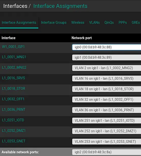
The "Interfaces" dashboard widget summarizes an overview similar to the following table.
| Interface | Speed / Duplex | Default Gateway |
|---|---|---|
| W1_0001_ISP1 | 1000baseT <full-duplex> | 100.127.248.101 |
| L1_0001_MNG1 | 1000baseT <full-duplex> | 172.21.1.1 |
| L1_0002_MNG2 | 1000baseT <full-duplex> | 172.22.2.1 |
| L1_0016_SRVS | 1000baseT <full-duplex> | 10.10.16.1 |
| L1_0018_STOR | 1000baseT <full-duplex> | 10.10.18.1 |
| L1_0032_OFF1 | 1000baseT <full-duplex> | 10.10.32.1 |
| L1_0036_PRNT | 1000baseT <full-duplex> | 10.10.36.1 |
| L1_0251_IOTD | 1000baseT <full-duplex> | 172.31.251.1 |
| L1_0252_DMZ1 | 1000baseT <full-duplex> | 172.31.252.1 |
| L1_0253_GNET | 1000baseT <full-duplex> | 172.31.253.1 |
We will continue with our configuration of pfSense in the following section.
3.3 Firewall Configuration in pfSense
In pfSense, the default firewall policy for interfaces is to deny all incoming traffic by default. This means that unless specific firewall rules are configured to allow traffic, all incoming connections to interfaces will be blocked.
When you create firewall rules, you are essentially specifying what traffic is allowed or denied for a particular interface. The rules are processed in order, from the top to the bottom, and the first rule that matches the traffic criteria is applied. If no rule matches, the default deny rule at the end of the rule set is applied.
It's important to configure firewall rules appropriately based on your network requirements to ensure that traffic flows as intended and that your network remains secure.
3.3.1. Default Firewall Rules
Let's establish a standard set of firewall rules that can be universally applied across all interfaces. Certain types of traffic are inherently permissible, and our goal is to craft efficient and effective firewall rules. To achieve this, we'll start by defining IP and Port Aliases. This strategic approach enhances the clarity and optimization of our firewall rule configuration.
3.3.1.1. IP Aliases
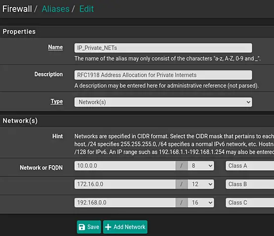
We will create the following IPv4 alias:
- Name: IP_Private_NETs
Description: RFC1918 Address Allocation for Private Internets - Type: Networks
- Network or FQDN: 10.0.0.0 /8
Descripton: Class A - Network or FQDN: 172.16.0.0 /12
Description: Class B - Network or FQDN: 192.168.0.0 /16
Description: Class C
First Navigate to "Firewall" > "Aliases" and next click on "Add" (in the "IP" tab).
Fill out the details. To add multiple networks, click "Add network". This will add a new line.
Save and Apply the changes. The end result will look similar to the following screenshot.
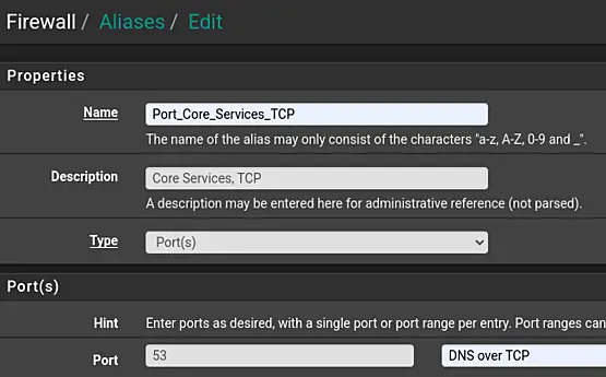
3.3.1.2. Port Aliases
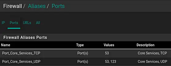
We will create the following Ports Aliases:
- Name: Port_Core_Services_TCP
- Description: Core Services, TCP
- Type: Port(s)
- Port: 53
Description: DNS over TCP
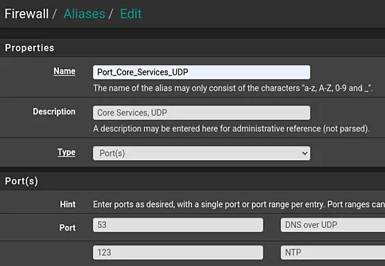
- Name: Ports_Core_Services_UDP
- Description: Core Services, TCP
- Type: Port(s)
- Port: 53
Description: DNS over UDP - Port: 123
Description: NTP
First Navigate to "Firewall" > "Aliases" and next click on "Add", in the "Ports" tab.
Fill out the details. To add multiple ports, click "Add Port". This will add a new line.
Save and Apply the changes.
The end result will look similar to the following screenshots.
3.3.1.3. Add Firewall Rules (floating)
Firewall rules can be implemented on a specific interface or as floating rules. The former applies to ingress traffic on the designated interface (referred to as "in" or incoming in pfSense documentation), while the latter can be enforced on any interface. It's essential to recognize that floating rules take precedence over regular interface rules. Additionally, it's worth noting that floating rules are versatile, not restricted to inbound traffic only; they can also be configured for outbound traffic by selecting "out" or for bidirectional traffic by choosing "any."
Exercise caution when working with floating rules, as their behavior may not be immediately intuitive to everyone.
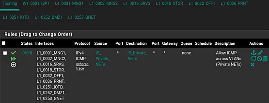
Let's establish a floating rule for ICMP. This is to graciously allow hosts to exchange pings across VLANs – unless, of course, it's a mysterious entity knocking on the network's door. No entry for big bad hackers!
First navigate to "Firewall" > "Rules". Next click "Floating". Now we can create the rule by clicking on "Add". Don't worry about the up or down arrow. This is the first rule. If there are more rules, then these can be move by dragging the specific rules up and down.
We will construct the following rule:
- Action: Pass
- Quick: check the tickbox
- Interface: select all the local interfaces
These are all the interfaces excluding "Any" and the WAN
Use the SHIFT to define a range of interfaces.
Use the CTRL to select or deselect individual interfaces. - Direction: in
We will look at traffic which enters the interface. - Address Family: IPv4
- Protocol: ICMP
- ICMP Subtypes: select both "Echo request" and "Traceroute" using CTRL.
- Source: Address Alias; IP_Private_NETs
- Destination: Address Alias; IP_Private_NETs
- Description: Allow ICMP across VLANs (Private NETs)
Save and Apply the changes.
This should result in the following floating rule.
Now, given the specialized nature of floating rules, and considering that many firewall configurations may not require them, we'll proceed with regular interface rules. If you find floating rules intriguing, you can explore more details in the documentation: Floating Rules Documentation.
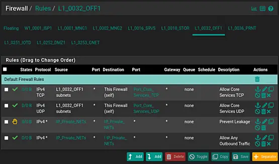
3.3.1.4. Add Firewall Rules (interface)
Recall our IP and port aliases? We're now incorporating them into our interface rules. While we could build floating rules, we've opted for interface rules to maintain a simpler configuration, even though this approach requires a bit more effort. The advantage, however, lies in the ability to easily duplicate firewall rules across interfaces, offsetting the additional workload.
Let's navigate to "Firewall" > "Rules." For now, we'll leave the management interfaces untouched and start with "L1_0032_OFF1." This approach aligns with the user's perspective, focusing on rules specific to the Office LAN.
Begin by clicking "Add" (either the button with the up or down arrow).
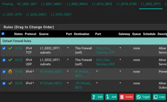
Rule 1:
- Action: Pass
- Interface: L1_0032_OFF1
- Address Family: IPv4
- Protocol: TCP
- Source: L1_0032_OFF1 subnets
- Destination: This Firewall (self)
- Destination Port Range: (other); Port_Core_Services_TCP
- Description: Allow Core Services TCP
Please Save and Apply the changes.
Now, click the "Add" button with the arrow pointing downwards.
Rule 2:
- Action: Pass
- Interface: L1_0032_OFF1
- Address Family: IPv4
- Protocol: UDP
- Source: L1_0032_OFF1 subnets
- Destination: This Firewall (self)
- Destination Port Range: (other); Port_Core_Services_UDP
- Description: Allow Core Services UDP
Please Save and Apply the changes.
These two rules allow specific TCP and UDP traffic from the Office LAN once it flows into the interface. The destination is the firewall itself, serving as a DNS and NTP server.
You might notice the absence of a rule for DHCP and outbound traffic. No rule is needed for DHCP traffic, as pfSense handles it by default. We only need to create an outbound rule if we want to permit traffic from the interface to the internet.
Rule 3:
- Action: Reject
- Interface: L1_0032_OFF1
- Address Family: IPv4
- Protocol: Any
- Source: Address or Alias; IP_Private_NETs
- Destination:
- Select "Address or Alias"
- Destination Address: IP_Private_NETs
- Description: Prevent Leakage
Now, click the "Add" button with the arrow pointing downwards.
Rule 4:
- Action: Pass
- Interface: L1_0032_OFF1
- Address Family: IPv4
- Protocol: Any
- Source: Address or Alias; IP_Private_NETs
- Destination:
- Check the tick box "Invert match"
- Select "Address or Alias"
- Destination Address: IP_Private_NETs
- Description: Allow Any Outbound Traffic
We might want to add a separator to clarify our rules.
Click "Separator." Next, enter the following description: "Default Firewall Rules." Click the green color ball. Next, click "Save." Finally, drag the new separator to the top of the rule set and click Save.
The final appearance should mirror the screenshot below, paying special attention to the exclamation mark indicating the inverse rule at the end of the rule set.

3.3.1.4. Replicate Firewall Rules
To replicate this firewall ruleset for another interface, check the upper-left checkbox and click 'Copy.'
Ensure to select the 'Convert interface definitions' option, then click 'Paste' and apply the changes.
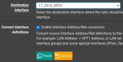
Note that the Separator won't be copied, as it's currently not possible. Please create the Separator 'Default Firewall Rules' for this interface to complete the steps.
Repeat these steps for the other interfaces starting with "L1_"
While we'll keep this rule for outbound traffic as is for now, it's advisable to replace it with a set of rules allowing only necessary outbound traffic for servers.
In this context, a widely recommended approach is to establish an 'Exceptions' Separator at the top of the firewall ruleset and position outbound rules directly beneath it. This practice provides a structured way to manage exceptions, making it easier to locate and modify rules when necessary. To achieve the desired effect, simply disable the outbound rule at the end, ensuring a balanced and controlled traffic flow.
For additional details on Managing Firewall Rules, refer to the Netgate Docs. Explore this link for an in-depth study, as it's a crucial aspect of pfSense configuration.
In the next section, we will briefly explore some important services of the pfSense firewall, such as DHCP and DNS.
3.4. pfSense Services
DHCP and DNS are crucial for network functionality, providing automation and organization in the assignment of IP addresses and the translation of domain names into IP addresses.
3.4.1. DHCP
DHCP (Dynamic Host Configuration Protocol) is a network protocol that automatically assigns IP addresses and other network configuration information to devices on a network. In pfSense, the DHCP service helps manage and distribute IP addresses dynamically, making it easier to connect devices to the network without manual configuration.
In the context of this article, it is important to know how to enable and configure DHCP.
Steps to Enable and Configure DHCP.
- Navigate to "Services" > "DHCP Server".
- Check the "Enable DHCP server on (select the interface)" box to activate the DHCP service for the desired interface.
- Configure the DHCP settings, including the range of IP addresses to be assigned, lease time, and additional options if needed.
- Save and Apply the changes to make the DHCP service operational.
These steps will help you effectively configure DHCP in pfSense.
For the Office network (L1_0032_OFF1) this should look like the following.
- Navigate to "Services" > "DHCP Server".
- Check the "Enable DHCP server on (select the interface)" box to activate the DHCP service for the desired interface.
- Configure the DHCP settings:
- Address Pool Range: (from) 10.10.32.101 (to) 10.10.32.200
- NTP Server 1: 10.10.32.1
- Save and Apply the changes to make the DHCP service operational.
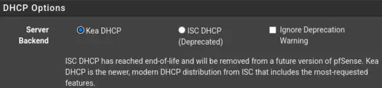
Important to note is that ISC DHCP has reached end-of-life and will be removed in a future version of pfSense. Administartors are encouraged to switch to Kea DHCP. Switching is a matter of a few clicks: "System" > "Advaned" > "Networking": check "Kea DHCP" and click on "Save".
3.4.2. DNS
DNS (Domain Name System) is a system that translates human-readable domain names (like www.ict-diensten.com) into IP addresses that computers use to identify each other on a network. In pfSense, the DNS service ensures efficient and accurate domain name resolution, facilitating seamless communication between devices using domain names rather than IP addresses.
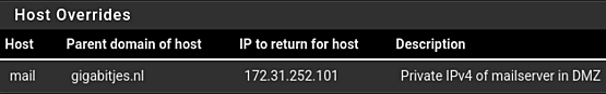
In the context of this article, it is important to know how to add Host Overrides and Domain overrides to pfSense's DHCP server.
Steps to Add Host Overrides and Domain Overrides:
- Navigate to "Services" > "DNS Resolver".
- Under the "Host Overrides" or "Domain Overrides" section, click on "Add" to add a new entry.
- Enter the necessary information, including the hostname, domain, and corresponding IP address.
- Save and Apply the changes to update the DNS settings.
These steps will help you effectively configureDNS services in pfSense.
Imagine you're using a mail server named mail.gigabitjes.nl, and its public IPv4 in the A record is 123.123.123.101. However, within the LAN, this server is recognized with the IPv4 address 172.31.252.101. In such a scenario, referring to the public IPv4 from the LAN is not practical. Setting a host override to the private IPv4 is a useful solution. This host override would look like the follwoing screenshot.
In the next section, we will briefly look at VLAN configuratoin on switches. We will switch between the interface of the switch and the web interface of pfSense for the required firewall rules.
3.5. Switch configuration
In our network, network switches play a crucial role in supporting a variety of devices such as switches, access points, servers, and workstations.
For an efficient network design, it's essential to establish a structured network connection scheme to avoid daisy-chained switches and potential bottlenecks. In this setup, we designate a core switch that serves as the central point. All other switches connect to this core switch, functioning as access switches. The connections from the core switch to the access switches are referred to as downlinks, while the connections from the access switches to the core switch are termed uplinks. This hierarchical configuration ensures a well-organized and scalable network infrastructure.
We will begin by assigning an IPv4 address to the switch and incorporating VLANs into the switch's VLAN configuration.
3.5.1. Preperations
Before configuring our (first) switch, it needs to be assigned an IPv4 address from the management VLAN [L1_0001_MNG1].
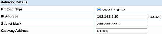
To start, I connected port 24 of an HP 1810-24g switch to the LAN interface of the pfSense firewall. Subsequently, I linked my laptop to port 23. I assigned a static IPv4 address, 192.168.2.123, with a subnet mask of 255.255.255.0 [/24] to my laptop. This step is taken to modify the default IPv4 address of the switch.
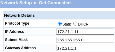
Following this, I changed the switch's IPv4 address to 172.21.1.11, with a subnet mask of 255.255.255.0 [/24]. The default gateway IPv4 was set to 172.21.1.1.
To ensure accurate IPv4 settings, I briefly disconnected the network cable from my laptop. Given that I'm using Linux, I could maintain DHCP settings while also setting a static IPv4 within the 192.168.2.0/24 network initially used by the switch.
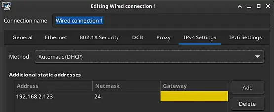
The default and updated settings are depicted in the screenshots below.
To prevent DHCP conflicts, I adjusted the DHCP pool of L1_0001_MNG1, modifying the range from 172.21.1.201 to 172.21.1.230 in the pfSense firewall. To do this, I navigated to "Services" > "DHCP Server" > "L1_0001_MNG1" and modified the range in the 'Primary Address Pool' section. Additionally, I noticed that the NTP Server 1 was not set. Although optional, I set it to 172.21.1.1. Finally, I saved and applied the changes.
3.5.2. VLAN Configuration
We are ready to implement the required changes to our switch. The focus will be on VLANs.
3.5.2.1. Network Overview
The following overview will be used.
| Interface | VLAN tag | Priority | Name | Subnet | Gateway | Description | Examples |
|---|---|---|---|---|---|---|---|
| igb1 (lan) | 1 | - | L1_0001_MNG1 | 172.21.1.0/24 | 172.21.1.1 | Management 1 | Switches, access points |
| igb1 (lan) | 2 | - | L1_0002_MNG2 | 172.22.2.0/24 | 172.22.2.1 | Management 2 | Hypervisor(s), KVM-over-IP |
| igb1 (lan) | 16 | - | L1_0016_SRVS | 10.10.16.0/24 | 10.10.16.1 | Server VMs | Server VMs |
| igb1 (lan) | 18 | - | L1_0018_STOR | 10.10.18.0/24 | 10.10.18.1 | Storage | Network Attached Storage (NAS) |
| igb1 (lan) | 32 | - | L1_0032_OFF1 | 10.10.32.0/24 | 10.10.32.1 | Workstations | Desktop and laptop computers |
| igb1 (lan) | 36 | - | L1_0036_PRNT | 10.10.36.0/24 | 10.10.36.1 | Peripherals | Printers |
| igb1 (lan) | 251 | - | L1_0251_IOTD | 172.31.251.0/24 | 172.31.251.1 | Internet of Things | Solar panel inverters |
| igb1 (lan) | 252 | - | L1_0252_DMZ1 | 172.31.252.0/24 | 172.31.252.1 | DMZ | Web and mail server |
| igb1 (lan) | 253 | - | L1_0253_GNET | 172.31.253.0/24 | 172.32.253.1 | Guest Network | Guest Wi-Fi network |
Before we can get started, we need to determine which VLANs will be configured on which ports. This particular HP switch has 24 Gigabit ethernet ports (ports 1-24) and two SFP+ slots (ports 25-26). Our port configuration will be as follows. You will notice the core switch will also be used as an access switch.
| Port | PVID | Tagged VLANs | Purpose |
|---|---|---|---|
| 01 | 32 | Access Port, Workstations | |
| 02 | 32 | Access Port, Workstations | |
| 03 | 32 | Access Port, Workstations | |
| 04 | 32 | Access Port, Workstations | |
| 05 | 32 | Access Port, Workstations | |
| 06 | 32 | Access Port, Workstations | |
| 07 | 32 | Access Port, Workstations | |
| 08 | 32 | Access Port, Workstations | |
| 09 | 32 | Access Port, Workstations | |
| 10 | 32 | Access Port, Workstations | |
| 11 | 32 | Access Port, Workstations | |
| 12 | 32 | Access Port, Workstations | |
| 13 | 36 | Access Port, Printer | |
| 14 | 36 | Access Port, Printer | |
| 15 | 251 | Access Port, IoT, NVR camera system | |
| 16 | 251 | Access Port, IoT, Inventor (solar panels) | |
| 17 | 18 | Access Port, Storage | |
| 18 | 18 | Access Port, Storage (reserved) | |
| 19 | 1 | 2,16,18,32,36,251,252,253 | Downlink, hypervisor |
| 20 | 1 | 2,16,18,32,36,251,252,253 | Downlink, hypervisor (reserved) |
| 21 | 1 | 2,16,18,32,36,251,252,253 | Downlink, switch or AP (reserved) |
| 22 | 1 | 2,16,18,32,36,251,252,253 | Downlink, switch or AP (reserved) |
| 23 | 1 | 2,16,18,32,36,251,252,253 | Downlink, switch (reserved) |
| 24 | 1 | 2,16,18,32,36,251,252,253 | Uplink, firewall |
| 25 | 1 | 2,16,18,32,36,251,252,253 | Downlink, switch (reserved) |
| 26 | 1 | 2,16,18,32,36,251,252,253 | Downlink, switch (reserved) |
3.5.2.2. VLAN Configuration
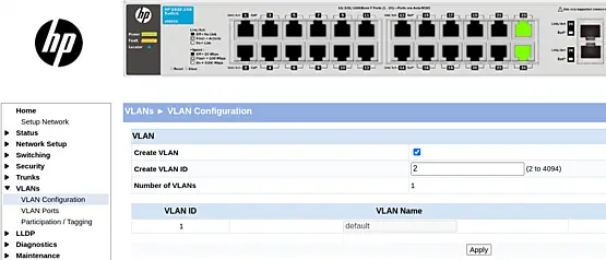
Let's proceed with the VLAN configuration on the HP 1810-24g switch. Additional switches, such as ZyXEL and TP-Link, will be integrated into this document in the upcoming revision.
Access the switch's web interface by navigating to its IPv4 address. Once logged in, we can begin adding VLANs.
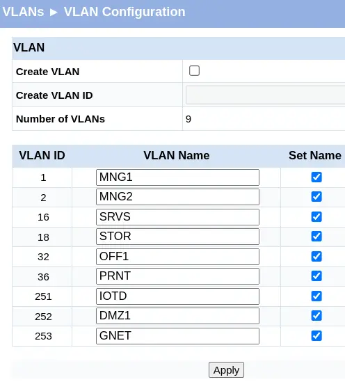
On this HP switch, go directly to "VLANs" > "VLAN Configuration." Creating a VLAN is a simple process: check the box next to "Create VLAN," enter the VLAN ID, and click "Apply."
Repeat this process for the remaining VLANs.
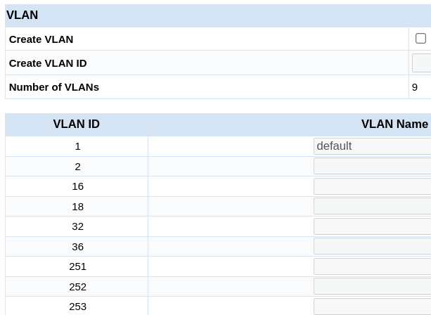
Keep in mind that the VLAN Name is not set initially. Activate the corresponding text field by checking the checkbox, fill in the VLAN Name column, and click "Apply" to complete the process.
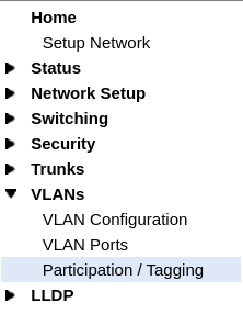
Now, click "Participation-/Tagging."
Select the VLAN and define the tagging. The initial screen looks like the following screenshot.
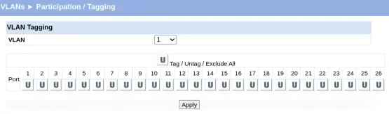
Change the VLAN from 1 to 32 and start tagging the VLAN to the ports. Ports 01-12 will be untagged, and Ports 20-26 will be tagged. Click "Apply."
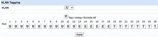
The switch may show a warning about the management VLAN, which is expected. Ignore this warning, as our laptop is not connected to one of the ports in the range 01-12.
172.21.1.11 says

Management port is not configured.
Configuring untagged membership on non-management VLAN may disrupt the web connectivity.

Do you wish to continue?

Cancel OK
Another warning may appear, indicating that a port cannot be a member of two untagged VLANs.
172.21.1.11 says

Ports - 1,2,3,4,5,6,7,8,9,10,11,12 can have only one untagged VLAN membership.
If the port is already untagged VLAN member in one VLAN and any other new VLAN is selected for untagged membership,
then the port will be excluded from previously untagged VLAN if any).

Do you wish to continue?

Cancel OK
Proceed to change the participation for VLAN 36.
As shown in the screenshot below, you'll observe that ports 13 and 14 are untagged. This allows us to connect a device to either port 13 or 14, making it suitable for accommodating two printers.
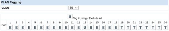
Next, change the participation of the remaining VLANs. Note that VLANs 252 and 253 only need to be added tagged to Ports 19-26.
Congratulations! For now, we have completed building our network. Additional changes will be applied once our hypervisor is up and running. Let's swiftly move on to building our Proxmox Hypervisor in the next chapter!
4. Building a Server Infrastructure
This chapter covers the installation and configuration procedure of Proxmox Virtual Environment (VE).
4.1. Minimum Hardware Requirements
Refer to the Proxmox website for minimum hardware recommendations for both production and evaluation environments.
For testing purposes, the requirements are modest:
- CPU: 64-bit (Intel EMT64 or AMD64), Intel VT/AMD-V capable CPU/Mainboard (for KVM full virtualization support)
- Minimum 1 GB RAM
- Hard drive
- One NIC
Production requirements are also reasonable; please consult the Hardware Requirements section for more details.
4.2. Obtaining the Proxmox Installation Image
The Proxmox installation image is available on the Proxmox website. Obtaining the Proxmox Virtual Environment ISO is straightforward. The next step is to write the ISO image to a USB Memstick.
4.3. Preparing Installation Media
Refer tp the Proxmox Wiki page and the Proxmox website for recommended procedures to prepare installation media. Please check the section on Preparing Installation Media. Note that the procedure is similar to pfSense, with the key difference being that Proxmox is only available in ISO format.
4.3.1. Linux
For Linux, the recommended process involves utilizing the `dd` command:
dd bs=1M conv=fdatasync if=./proxmox-ve_*.iso of=/dev/sdX
Refer to the Prepare Media section on the Proxmox website for exact details.
Instead of the recommended procedure, Ventoy was used. Ventoy is not listed in the Proxmox documentation. Although not listed in Proxmox documentation, it was employed successfully; although a CI version of Ventoy had to be used as described in issue 2657.
4.3.2. MacOS
For MacOS, use the hdiutil command.
hdiutil convert proxmox-ve_*.iso -format UDRW -o proxmox-ve_*.dmg
Please consult the section Prepare Media on the Proxmox website for the exact details.
4.3.3. Windows
For Windows, one recommendation is to use Rufus in DD mode.
A note from the Proxmox Admin Guide advises selecting "DD mode" when prompted and avoiding the download of a different version of GRUB.
Source: Proxmox Admin Guide, section: Prepare Media.
4.4. Proxmox VE Installation Process
The installation process of Proxmox VE is straightforward and less intensive than pfSense.
4.4.1. Booting
Boot the computer with the prepared installation media. Select "Install Proxmox VE (Graphical)" to begin the installation.
Note: During boot, if the process stalls during country detection, unplug the network cable, reboot, select "Install Proxmox VE (Graphical)" again, and reconnect the cable after the End User Agreement (EULA) is presented.
4.4.2. EULA
Click "I agree" at the EULA.
4.4.3. Partitioning
Select the target hard disk. The server's storage configuration is as follows:
- /dev/sda 465.76 GiB Samsung SSD 860
- /dev/sdb 465.76 GiB Samsung SSD 860
- /dev/sdc 465.76 GiB Samsung SSD 860
- /dev/sdd 465.76 GiB CT500MX500SSD4
The chosen target hard disk is /dev/sdd.
An alternative option is to use "zfs (RAIDZ-1)" for the first three SSDs and ext4 for the latter SSD. Click "Next" to proceed.
4.4.4. Location and Time Zone Selection
During installation, select the location and time zone. For example:
- Country: Netherlands
- Time zone: Europe/Amsterdam
- Keyboard Layout: U.S. English
Click "Next" to continue.
4.4.5. Administration Password and Email Address
Set a password and provide an email address when prompted by the installer. Click "Next" afterward.
4.4.6. Management Network Configuration
Network configuration is crucial. Select the following, ensuring to adjust the hostname (FQDN).
- Management Interface: eno1 {mac} (e1000e)
- Hostname (FQDN): pve101.lan.gigabitjes.nl
- IP Address (CIDR): 172.21.1.101
- Gateway: 172.21.1.1
- DNS Server: 172.21.1.1
Click "Next".
Please take note that our hypervisor will be positioned in VLAN1, deviating from the original network design, which specified VLAN2. At this stage, opting for VLAN2 might be overly complex, as it requires a more complicated VLAN setup.
4.4.7. Finalizing the installation
Review the summarized decisions and click "Install." Once the installation is complete, the system will reboot.
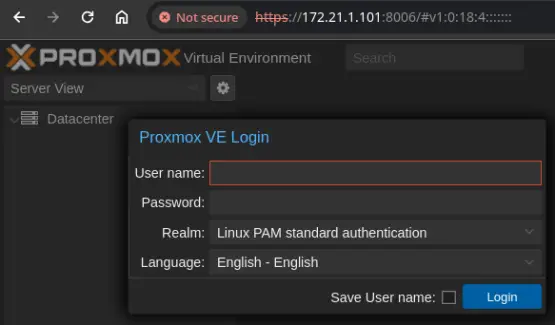
4.5. Proxmox Configuration Procedure
Once Proxmox VE is installed, the configuration process begins. Open a web browser and connect to https://172.21.1.101:8006.
4.5.1. Subscription and updates
Proxmox VE Subscriptions
It is advisable to opt for a Proxmox subscription, providing access to the stable Proxmox Enterprise Repository for reliable software updates, security enhancements, and enterprise-grade technical support.
Proxmox VE No-Subscription Repository
For testing and non-production use, the Proxmox VE No-Subscription Repository is recommended. It doesn't require a subscription key.
For this article, the Proxmox VE No-Subscription Repository will be used.
To set the No-Subscription Repository:
- Navigate to PVE under Datacenter and click on Shell.
- Open sources.list with a text editor like vi or nano.
- Add the Proxmox VE No-Subscription Repository to /etc/apt/sources.list:
deb http://download.proxmox.com/debian/pve bookworm pve-no-subscription
Save the changes and close the editor. - Disable enterprise repositories for Ceph and Proxmox:
Open /etc/apt/sources.list.d/ceph.list and comment out the repository:
#deb https://enterprise.proxmox.com/debian/ceph-quincy bookworm enterprise
Open /etc/apt/sources.list.d/pve-enterprise.list and comment out the repository:
#deb https://enterprise.proxmox.com/debian/pve bookworm pve-enterprise
Save the changes and close the editor. - Check and install updates:
apt update && apt -y upgrade - Optional: remove the subscription nag:
sed -Ezi.bak "s/(Ext.Msg.show\(\{\s+title: gettext\('No valid sub)/void\(\{ \/\/\1/g" /usr/share/javascript/proxmox-widget-toolkit/proxmoxlib.js && systemctl restart pveproxy.service
Refer to John's Computer Service with regards to removing the subscripton nag.
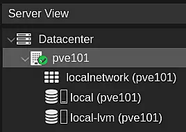
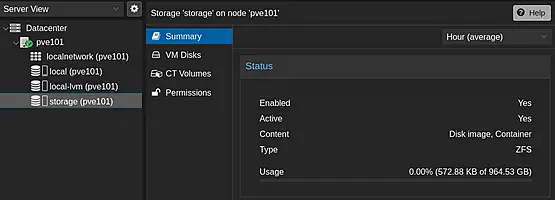
4.5.2. Storage
When expanding PVE in the left pane, notice the local storage. Add the three SSDs for VM and Container storage.
- Click ZFS (under Disks) in the second pane.
- Click Create ZFS, select disks, name (e.g., 'storage'), choose RAID Level (e.g., RAIDZ), and click Create.
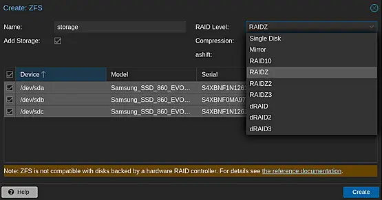
Now, create VMs and Containers and store their disks and volumes on the ZFS storage.
4.5.3. VLANs
Before creating VMs and CTs, sort VLANs to connect them to the correct networks.
Click on Network to open the overview (take note of the Linux Bridge vmbr0).
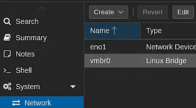
Click Create and select Linux VLAN.
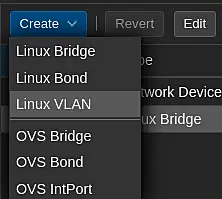
Enter the details of the VLAN and click Create.
- Start with the brdige name and then enter the VLAN number (separated by a dot).
- Do not enter the IPv4/CIDR.
- For clarity enter the VLAN name in the comment field.
- Click Create.
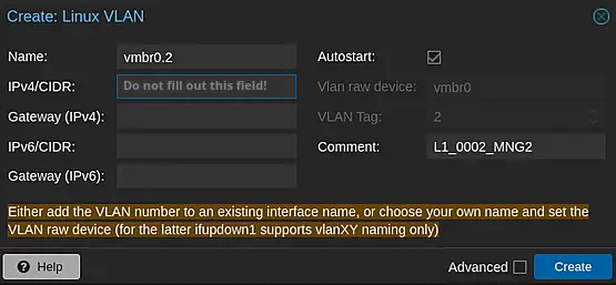
Upon the successful addition of VLAN 2, the resulting configuration will resemble the screenshot below.
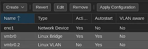
Repeat this procedure for the other VLANs.
Apply the configuration by clicking Apply Configuration.
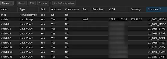
Some important considerations:
- Routing problems may arise as soon as IPv4/CIDR information is entered for VLANs. This does not affect traffic between VMs and physical network nodes, but it does affect traffic between the PVE and VMs/physical network nodes. This can cause confusion for troubleshooting. Be warned!
- Open vSwitch (OVS) as an alternative to Linux switching:
One Linux bridge and Linux VLANs are used. You may consider choosing an OVS Bridge and OVS InstPorts. The point is that the existing bridge must first be removed. Thus, if you prefer to use OVS: only apply the changes once at least the new OVS Bridge has been created correctly. You are being urged to create a copy of `/etc/networking/interfaces` in advance. You may need to use a (physical) keyboard and monitor in case something goes terribly wrong with the network configuration.
4.5.4. VM & CT Installation Sources
ISO Images are used for our VMs. CT Templates are used for Containers.
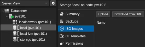
4.5.4.1. ISO Images
Use ISO images of Setup CDs/DVDs to install VMs.
Click ISO Images under 'local (pve101)' and Upload or Download from URL to add an ISO Image.
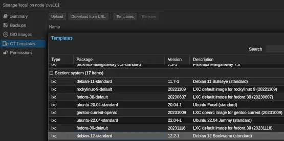
4.5.4.2. CT Templates
Containers are resource-efficient. CT Templates are required to create Containers.
Click CT Templates and then Templates to list available templates. Download the desired template.
4.6. Proxmox Backups
Backups are indispensable. Add backup storage and enable backups for VMs and CTs.
4.6.1. Backup targets and tasks
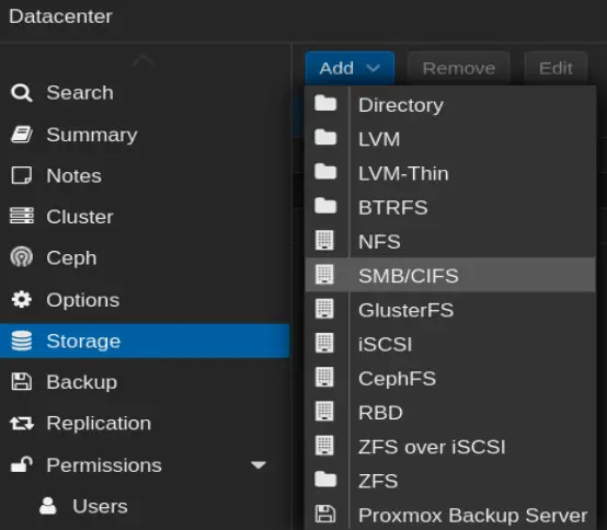
An easy backup method is adding an SMB/CIFS storage location. Add a NAS via Storage under Datacenter. For details, consult the Proxmox VE Wiki chapter on Storage.
Find the Backup option under Storage and refer to the Backup and Restore in the Proxmox Wiki for an detailed overview.
Incorporating a backup target and creating backup schedules is a straightforward process. To enhance mail notifications, it's advisable to utilize a relayhost. An informative example can be found on the Proxmox Forum in the tutorial titled [TUTORIAL] Get Postfix to send Notifications (Email) Externally). Configuring mail notifications is crucial for monitoring the success of backups. It's worth noting that the relayhost can be our self-hosted mail server, a topic we will delve into in the next chapter!
5. Internet-exposed Services
Considerations for Hosting Your Mail and Web Server
An important decision to contemplate is whether to host your own mail and web server. While alternatives exist, such as utilizing a Virtual Private Server (VPS) or relying on external hosting services, this article operates under the assumption of self-hosting on dedicated hardware.
If you genuinely don't feel comfortable running internet-exposed services, it might be better to refrain from doing so. Security and comfort are paramount considerations in deciding how and where to host critical services!
Self-hosting concept
In our network, there will be both internet-exposed and internal services. The former will include services like web and mail servers, which are crucial to set up and secure early in the process. These internet-exposed services act as the face of our network, requiring careful configuration for accessibility and protection.
We'll start by focusing on internet-exposed services, treating the setup of a mail server and web server as valuable exercises. This approach allows us to implement and secure critical services before delving into internal services like Domain Controllers and File Servers, which we prefer not to expose to the internet. Prioritizing the configuration and security of these externally facing services is a fundamental practice to ensure both accessibility and protection.
As we progress, we'll also explore internal services in the next chapter, ensuring a comprehensive and well-organized network infrastructure.
5.1. Routing traffic
To enable routing for our internet-exposed services, certain requirements must be met. In some cases, existing internet connections may not meet these criteria, and changing the connection might not be feasible. In such situations, a workaround is necessary.
An example is the need to establish a valid Pointer (PTR) record in DNS for hosting a mail server. Typically, this PTR record is configured by the operator of the public IP, often the Internet Service Provider (ISP). It is essential to ensure that the public IP address associated with the internet connection has a valid PTR record. The Fully Qualified Domain Name (FQDN) of the server must align with the outcome of a PTR lookup performed on the public IP address. Failure to achieve this alignment poses a risk to the successful delivery of email messages. In cases where the internet service provider cannot configure a PTR record, a workaround becomes imperative. This section details potential strategies for implementing such a workaround.
One of the possible solutions is to introduce a GRE tunnel. Generic Routing Encapsulation (GRE) is a tunneling protocol designed to encapsulate various network layer protocols within virtual point-to-point or point-to-multipoint links over an Internet Protocol network.
The selection of GRE is intentional. While it doesn't encrypt the traffic between the endpoints, GRE is lightweight and versatile, making it well-suited for routing email and web traffic.
We'll establish a GRE tunnel to efficiently route traffic between our pfSense firewall and a cost-effective Virtual Private Server (VPS). By leveraging the public IPv4 address of the VPS, we'll manage incoming traffic. This traffic will be transported through the GRE tunnel to our server VM, operating on Proxmox.
In summary, we need to configure the following components.
- Set up a VPS with (Debian) Linux,including network and GRE configuration.
- Establish IPTables firewall rules on the VPS.
- Configure GRE and rules on pfSense.
- Set up a VM running ISPConfig server on (Debian) Linux, responsible for hosting the mail and web server.
5.1.1. Choosing a VPS provider
Requirements
When selecting a Virtual Private Server (VPS) provider, it's crucial to choose one that aligns with specific requirements. Look for a provider that allows the use of a public IPv4 address, permits the configuration of a Pointer (PTR) record, and offers unlimited traffic.
For the purposes of this article, Strato has been chosen as the VPS provider. Strato, a reputable web hosting company, offers a range of solutions, including Virtual Private Servers (VPS). Among the available products, the VPS LINUX MINI VC1-1 and VC1-2 are suitable choices. As of the time of writing, the monthly cost for a VC1-1 is a mere €1. While this mini VPS meets the specified requirements, the VC1-2 is selected for additional versatility, as the author intends to utilize this VPS for various other services as well.
Availability
The VC1-1 and VC1-2 VPS plans are available on Strato's Dutch and German websites. Although there is a Spanish website, it's uncertain whether it features the mini-VPS category. Notably, Strato's UK and French websites do not appear to provide any Virtual Private Server options. While the author of this article does not have any experience with Ionos, it seems to be one of the cost-effective options worth considering (as an alternative to Strato UK).
Billing Information for Strato VPS (VC1-2)
Strato bills quarterly, and the initial invoice for the VC1-2 VPS is €6. The billing cycle spans one year, resulting in total annual costs of €24 excluding VAT. No additional setup costs apply.
Strato's order process
During the order process, a customer account will be created. After this step is completed, the order undergoes processing, which may take several hours. The Virtual Private Server (VPS) is then provisioned, arriving in a "bare" state. At this stage, the operating system can be installed. Once the operating system setup is complete, the root user can log in. Strato mandates SSH access using a certificate for secure connections, which is a sensible security measure.
This is how to create a SSH certificate for the VPS in Linux:
1. Open a terminal and type the following command:
ssh-keygen -t ecdsa
2. Enter a file name in which to save the key, such as "id_strato_vps," and press Enter when a passphrase is requested.
3. Copy the generated public key to the VPS. This is a crucial step in the staging process.
4. Finally, log in to the VPS using the following command:
ssh [email protected] -i $HOME/.ssh/id_strato_vps
Ensure to adjust the server name and the key as needed to establish the connection.
Please note: It's essential to set up a DNS A record for the server, corresponding to the chosen domain. The A record should point to the public IPv4 address of the VPS. This ensures proper domain resolution and allows users to reach your server using the designated domain name. Another essential step is to set the Pointer (PTR) Record. In most cases this has to be done in the admin panel of the VPS provider.
5.1.2. Customizations (VPS)
There are specific customizations required for the VPS.
5.1.2.1. Customizing Strato VPS
Packages
Ensure to install required packages.
apt update && apt -y install \
bzip2 \
cron \
dnsutils \
fail2ban \
iproute2 \
iptables \
mc \
nano \
net-tools \
unzip \
whois
Cloud-init Removal
It's recommended to remove Cloud-init, a software package automating cloud instance initialization during system boot, as it is unnecessary for our purposes.
touch /etc/cloud/cloud-init.disabled
dpkg-reconfigure cloud-init
apt-get purge cloud-init
rm -rf /etc/cloud/ && rm -rf /var/lib/cloud/
Although not mandatory, it's advisable to reboot.
reboot
Netplan
Configure the network setting via Netplan, specifically in the default file `/etc/netplan/50-cloud-init.yaml`. This file will be modified to include the configuration for the GRE tunnel.
network:
    ethernets:
        all:
            dhcp4: true
            dhcp6: true
            match:
                name: en*

    version: 2
Any warnings referencing Cloud-init can be ignored since it has been removed.
Now, add a GRE tunnel using the following example:
network:
    ethernets:
        all:
            dhcp4: true
            dhcp6: true
            match:
                name: en*

    tunnels:
        gre1:
        mode: gre
        local: 217.nnn.nnn.27
        remote: 77.nnn.nnn.155
        addresses: [172.30.250.2/29]

version: 2
Be sure to adjust the IPv4 for both local and remote. Here, "local" represents the VPS, "remote" represents the other connection point of the tunnel (e.g., a firewall), and the address represents the inner address of the GRE tunnel on the VPS side. Use 172.30.250.1/29 as the inner address for the other side of the tunnel (e.g., a firewall).
Firewall rules
To facilitate traffic routing, specific firewall rules need to be configured during the VPS boot process. This can be achieved through a firewall script. Download the fwall.sh script from Github and place it in `/opt/scripts`. Ensure that the script is executable.
mkdir /opt
mkdir /opt/scripts
cd /opt/scripts
wget "https://raw.githubusercontent.com/bhenstra/LiFiWall-Scripts/main/IPTables%20Forwarding%20GRE/fwall.sh"
nano fwall.sh
chmod +x fwall.sh
Adjust at least the variables "WL_SSH," "WL_GRE," and "INT_PUB." The variables are self-explanatory, with a brief comment preceding each one within the "BEGIN SETTINGS" and "END SETTINGS" blocks.
Finally, add the script to root's crontab.
crontab -e
Add the following line:
@reboot /opt/scripts/fwall.sh > /dev/null 2>&1
With these configurations in place, the VPS is prepared to accept and route traffic effectively.
5.1.3. Configuring pfSense
The other end of our GRE tunnel is the pfSense router/firewall. To establish this connection, we need to configure a GRE interface, linking it to the public IPv4 of the VPS.
Add and configure the required GRE interface via the option "GREs," located under "Interfaces" > "Assignments."
- Parent Interface: select the WAN interface (e.g. W1_0001_ISP1)
- Remote address: the public address of the VPS
- Local IPv4 tunnel address: 172.30.250.1
- Remote IPv4 tunnel address: 172.30.250.2
- Subnet in CIDR format: /29
- Check the option "Add Static Route"
- Enter a description for administrative reference
- Save and Apply the settings.
Express the GRE tunnel as an interface (the reason being to enable us to apply firewall rules).
- Click on "Interfaces" > "Assignments".
- Selec the GRE tunnel at "Available network ports" and click "Add".
- Save and Apply the changes.
- Edit the new interface by clicking it.
- Enable the interface
- Define a descripton "W1_0001_GRE0"
- Set the MTU to 1476.
Save and Apply the changes.
Although not required for the WAN interface, define firewall rules for the new GRE tunnel. First, create a port alias representing the accepted traffic.
Click "Firewall" > "Aliases" >"Ports". Click on "Add".
- Name: Ports_Ingress_GRE_TCP
- Description: Accepted TCP Ports for GRE
- Type: Port(s)
- Add the following ports, one per line; click "Add Port" to add a line:
- 25
- 80
- 443
- 465
- 587
- 993
Save and Apply Changes
Add a rule to accept ICMP traffic by clicking on "Firewall" > "Rules" > "W1_0001_GRE0". Click "Add" to create fhe following rule.
- Action: Pass
- Interface: "W1_0001_GRE0"
- Address Family: IPv4
- Protocol: ICMP
- ICMP Subtypes:
- Echo Request
- Traceroute
- Source: W1_0001_GRE0 subnets
- Destination: W1_0001_GRE0 subnets
- Description: Allow ICMP from GRE0 subnets
Save and Apply Changes
We will apply the port alias for the following NAT rule by clicking on "Firewall" > "NAT". Click "Add" to create the following NAT rule.
- Interface: W1_0001_GRE0
- Address Family: IPv4
- Protocol: TCP
- Destination: W1_0001_GRE0 address
- Destination port range:
- From port: other
- Custom: Ports_Ingress_GRE_TCP
- Redirect IP: Address or Alias: 172.31.252.103
- Redirect target port:
- Port: Other
- Custom: Ports_Ingress_GRE_TCP
- Description: Allow ingress traffic via GRE
Save and Apply Changes
Note: The IPv4 172.31.252.103 represents our VM running the ISPConfig server in DMZ. Feel free to choose another IPv4 as needed.
5.2. Installing ISPConfig
ISPConfig, an open-source Linux panel for managing multiple servers, will be installed within a Linux container on Proxmox. Customize the IPv4 (e.g. 172.31.252.103) and FQDN (e.g. s3.gigabitjes.nl) as needed.
5.2.1. Download Container Template
Please refer to "4.5.4.2. CT Templates" and download "debian-12-standard". This task will take a few seconds.
The default location for CT Templates is under "CT Templates"of the "local" storage option under the PVE.
5.2.2. Create Container
- Click "Create CT" to create a new contianer.
- Enter the required settings.
General
- Enter the CT ID: 103
- Enter hostname: s3
- Enter and confirm the desired root password
- Click Next
Template - Select the template: debian-12-standard_12.2-1_amd64.tar.zst
- Click Next
Disks - Select the storage (in our case it is "storage")
- Set the disk size (GB): eg "200"
- Click Next
CPU - Set the cores: e.g. "2"
- Click Next
Memory - Set the amount of Memory (MiB): e.g. "4096"
- Set swap (MiB): e.g. "8192"
- Click Next
Network - Leave the name and brdige as they are
- Set VLAN Tag: 252
- Enter the IPv4/CIDR: 172.31.252.103/24
- Enter the gateway IPv4: 172.31.252.1
- Click Next
DNS - Enter the DNS domain: e.g. "gigabitjes.nl"
- Enter the DNS server: 172.31.252.1
- Click Next
Confirm - Review and confirm the options by clicking on Finish.
- Select the new container and click "Console".
- Click "Start" to start the container.
5.2.3. Perfect Server Automated ISPConfig 3 Installation
The following steps are derived from the Perfect Server Automated ISPConfig 3 Installation on Debian 10 to Debian 12, Ubuntu 20.04 and Ubuntu 22.04 tutorial.
Click the container (s3) and select "Console". Login as root.
5.2.3.1. Update apt sources
Edit the apt sources.list file
nano /etc/sources.list
to reflect the following list:
deb http://deb.debian.org/debian bookworm main contrib

deb http://deb.debian.org/debian bookworm-updates main contrib

deb http://security.debian.org bookworm-security main contrib

deb http://deb.debian.org/debian bookworm-backports main contrib
5.2.3.2. Packages
As we move forward, we will follow the steps outlined in paragraph 5.2.3.2.2 to seamlessly upgrade essential software packages, ensuring the maintenance of system security and the optimization of overall performance. Emphasizing the importance of regular package upgrades, this practice is crucial for sustaining both system security and optimal performance.
5.2.3.2.1. Kernel
Containers are lightweight and use the kernel of the hypervisor. There is no need to install a new kernel for a container. Skip the following steps and continue with paragraph 5.2.3.2.2. Upgrading Packages.
When a VM is used, you might consider to install the latest cloud kernel. Lookup the latests Linux loud kernel with the following command:
apt update && apt-cache search linux-image | grep "cloud"
Pick and install the latests version. At the moment of writing this was "linux-image-6.5.0-0.deb12.4-cloud-amd64":
apt -y install linux-image-6.5.0-0.deb12.4-cloud-amd64
5.2.3.2.2. Upgrading Packages
apt update && apt -y upgrade
5.2.3.3. Reboot the container.
reboot
5.2.3.4. Run the auto installer
Login as root post-reboot. The procedure below is almost the same as described in the original tutorial. The differences are the way in which the hostname and domain are set and the fact that quotas cannot be used in a container. You will notice that "--no-quota" has been added to the installation command.
We can now run the auto-installer. The basic setup contains the following software packages (plus their dependencies): Apache2, PHP (versions 5.6 - 8.0), MariaDB, Postfix, Dovecot, Rspamd, BIND, Jailkit, Roundcube, PHPMyAdmin, Mailman, Webalizer, AWStats and GoAccess. You can easily choose not to use certain functions or install extra services by passing arguments to the installer. See Chapter 6 of the original tutorial for available command-line options.
Either opt for ISPConfig with Apache web server (5.2.3.4.1) or with Nginx web server (5.2.3.4.2).
5.2.3.4.1. Install ISPConfig with Apache web server
You can now run the script with arguments. For example, if you want a normal install with Apache web server and a port range for Passive FTP + unattended-upgrades, run:
wget -O - https://get.ispconfig.org | sh -s -- --use-ftp-ports=40110-40210 --unattended-upgrades --no-quota
The following steps are described in "5.2.3.4.3. Running the auto installer".
5.2.3.4.2. Install ISPConfig with Nginx web server
You can now run the script with arguments. For example, if you want a normal install with Nginx web server and a port range for Passive FTP + unattended-upgrades, run:
wget -O - https://get.ispconfig.org | sh -s -- --use-nginx --use-ftp-ports=40110-40210 --unattended-upgrades --no-quota
The following steps are described in "5.2.3.4.3. Running the auto installer".
5.2.3.4.3. Running the auto-installer
After some time, when prompted to reconfigure the complete server, type 'yes' and hit enter to start the installer.
WARNING! This script will reconfigure your complete server!
It should be run on a freshly installed server and all current configuration that you have done will most likely be lost!
Type 'yes' if you really want to continue:
Upon completion, note down the ISPConfig admin and MySQL root passwords.
[INFO] Your ISPConfig admin password is: 8ZxSEWakDgSLXv
[INFO] Your MySQL root password is: EhFrU3KYVLPVBbcJr2Js
5.2.3.5. Setting up the firewall
Configure the firewall via the ISPConfig (Web) UI. For port 8080 access, either allow the port in both the VPS and pfSense firewall or add a host override in pfSense. In light of this article we will opt for the latter.
Open the webUI of pfSense and click "Services" > "DNS Forwarder". Scroll down to "Host Overrides" and click Add. Enter the hostname (e.g. "s3"), the domain (e.g. "gigabitjes.nl") and the IPv4 (e.g. "172.31.252.103"). Enter a description (e.g. "Internal hosting server s3"). Save and Apply Changes.
Enter either the FQDN or IPv4 (e.g. "https://s3.gigabitjes.nl:8080" or "https://172.31.252.103:8080"). You can ignore the "certificate is not trusted" warning. Click advanced and proceed to the website.
Log in to the ISPConfig UI, and navigate to "System" > "Firewall". Next click "Add new firewall record".
For a normal setup, the ports to open are:
- TCP: 20,21,22,25,80,443,40110:40210,110,143,465,587,993,995,53,8080,8081
- UDP: 53
Please see chapter five of the original tutorial for further details.
5.2.3.6. Further reading
Refer to chapters six and seven of the the original tutorial for Advanced Options, useful tips (under Finalizing), and important notes regarding setting up mail (rDNS, SPF, DKIM). DNS considerations are crucial due to split DNS, impacting how DNS resolves for our hosting server within our LAN.
Refer to the ISPConfig 3 User Manual which is available for just €5 (exlusive VAT).
5.3. Websites and mail domains
Websites can be effortlessly added using the "Sites" option, while email domains can be incorporated through the "Email" option. The process is straightforward and aligns with the intuitive functionality expected from a hosting panel. In addition to the manual mentioned in the preceding paragraph, excellent Community Support is available.
While ISPConfig supports DNS, it is assumed that domains are managed outside ISPConfig via a DNS manager, typically a registrar or hosting provider.
To use such a domain, the DNS records must point to the public IPv4 of the VPS.
5.3.1. Brief illustration of A and CNAME records
An example of a A record for a website is:
example.com. 86400 IN A 93.184.216.34
When someone browses to "example.com", the IPv4 "83.184.216.34" is resolved. Just replace "example.com." with your own domain and "93.184.216.34" with the IPv4 of your VPS.
In addition to A records, it is common to work with CNAME records, functioning as aliases. For instance, FQDNs like "www.example.com" can act as an alias for "example.com." Failure to set such a CNAME record may result in missing visitors.
5.3.2. Brief illustration of MX records
An example of a MX record for a mail domain is:
example.com. 300 IN MX 0 mail.example.com.
When someone sends an email to e.g. [email protected], the mail server will try to deliver the message to mail.example.com. The host mail.example.com on the other hand requires a valid A record.
Replace "example.com." with the email domain and replace "mail.example.com." with the FQDN of your VPS, in the context of this article, it would be s3.gigabitjes.nl.
5.3.3. Brief illustration of SPF, DKIM and DMARC
Spam is a modern problem. There are several techniques to mitigate spam. Such techniques are a must to implement. Failing to implement a proper policy will result in problematic mail delivery.
Various DNS text records (TXT) are necessary for proper mail delivery. The SPF record is crucial and must include the FQDN or the public IPv4 of the VPS as an allowed sender. DMARC and DKIM are two other essential protocols. The latter can be easily enabled via ISPConfig. Once enabled, a digital signature is attached to the body and header of each outbound message for the email domain in question. ISPConfig will generate the required DNS record which has to be published in DNS (publishing the DNS record is not an automatic event).
DMARC establishes a policy informing receiving MX gateways about what to do with any inbound messages that cannot be validated in accordance with DKIM or SPF. This may involve discarding or quarantining all non-validated mail. The DMARC policy is published in DNS and may include a mail address to which mail systems can report rejected messages. This is valuable for the domain's operator as it helps monitor the delivery of messages.
The details are briefly described in the following paragraphs. While some redundancy exists in the elaboration, it serves the purpose of explaining the somewhat complex subject using different terminology, all while maintaining brevity.
5.3.3.1. SPF (Sender Policy Framework)
SPF is a mechanism to prevent sender address forgery. It allows domain owners to specify which mail servers are authorized to send emails on behalf of their domain.
Example SPF record:
v=spf1 ip4:203.0.113.101 include:_spf.example.com -all
In this example, the SPF record states that the mail can be sent from the IPv4 address 203.0.113.101 and includes the SPF records of _spf.example.com. The -all indicates a hard fail, meaning that if the server is not listed in the SPF record, the email will be rejected.
5.3.3.2. DKIM (DomainKeys Identified Mail):
DKIM adds a digital signature to emails, allowing the recipient to verify that the message was not altered in transit and that it actually came from the domain it claims to come from.
Example DKIM Record:
v=DKIM1; k=rsa; p=MIGfMA0GCSqGSIb3DQEBAQUAA4GNADCBiQKBgQCxLXFhjjUrU4yEh28qOrSXrJAEi9YZ5zOZkx3WENrRIZ6jyBQT35gYWvDjM6TAgDgSpwCjtgmAwr6JuFTEPTXvmSUGuJrkSj9rgjrgE+HxHjYsPFJmlqlwI+ywOo5e3C5L8vJzWvl98ZAF/ZdD+XW+D/wRZKw1H7Sn5yiy2S/wIDAQAB
This is a DKIM public key. The private key is used to sign outgoing emails, and the public key is published in the DNS. The selector (s=) is often used to identify the specific key for a given sending service.
5.3.3.3. DMARC (Domain-based Message Authentication, Reporting, and Conformance):
DMARC builds on SPF and DKIM to provide a way for email senders to authenticate their emails and request reporting on emails that fail authentication attempts.
Example DMARC Record:
v=DMARC1; p=quarantine; rua=mailto:[email protected]; ruf=mailto:[email protected]; sp=quarantine; adkim=s; aspf=s; fo=1
This DMARC record requests that emails failing authentication should be quarantined, and aggregate and forensic reports should be sent to [email protected] and [email protected], respectively. The adkim and aspf specify strict alignment for DKIM and SPF.
Remember to replace the example domains, keys, and email addresses with your actual information. Additionally, DNS records may take some time to propagate, so it's advisable to test and monitor the implementation.
Further reading: SIDN has published an informative article about the various protocols to keep mail traffic safe.
5.3.4. Querying DNS records
In Linux the command `dig` can be used to query DNS records. This is very useful, because it allows you to see how things have been set up by other parties.
Microsoft for instance uses the domain contoso.com in a lot of documentation. It is a useful practice to query on the contoso domain, to learn how DNS records look like.
5.3.4.1. Example: querying A record of contoso.com:
dig A contoso.com.
Results in:
; <<>> DiG 9.19.17-1-Debian <<>> A contoso.com.
;; global options: +cmd
;; Got answer:
;; ->>HEADER<<- opcode: QUERY, status: NOERROR, id: 46943

;; flags: qr rd ra; QUERY: 1, ANSWER: 5, AUTHORITY: 0, ADDITIONAL: 1
;; OPT PSEUDOSECTION:
; EDNS: version: 0, flags:; udp: 512
;; QUESTION SECTION:
;contoso.com. IN A

;; ANSWER SECTION:
contoso.com. 3394 IN A 20.112.250.133
contoso.com. 3394 IN A 20.236.44.162
contoso.com. 3394 IN A 20.231.239.246
contoso.com. 3394 IN A 20.70.246.20
contoso.com. 3394 IN A 20.76.201.171

;; Query time: 0 msec
;; SERVER: 172.21.1.1#53(172.21.1.1) (UDP)
;; [..]
5.3.4.2. Example: querying CNAME record of www.contoso.com:
dig cname www.contoso.com.
Restults in:
; <<>> DiG 9.19.17-1-Debian <<>> cname www.contoso.com.
;; global options: +cmd
;; Got answer:
;; ->>HEADER<<- opcode: QUERY, status: NOERROR, id: 2164
;; flags: qr rd ra; QUERY: 1, ANSWER: 1, AUTHORITY: 0, ADDITIONAL: 1

;; OPT PSEUDOSECTION:
; EDNS: version: 0, flags:; udp: 512
;; QUESTION SECTION:
;www.contoso.com. IN CNAME

;; ANSWER SECTION:
www.contoso.com. 3600 IN CNAME contoso.com.

;; Query time: 24 msec
;; SERVER: 172.21.1.1#53(172.21.1.1) (UDP)
;; [..]
5.3.4.3. Incorporating `grep`
We can find the SPF record for contoso.com with ease by incorporating the `grep` command to the `dig` command.
dig TXT contoso.com | grep spf
Results in:
contoso.com. 3030 IN TXT "v=spf1 include:spf.protection.outlook.com -all"
5.3.4.4. Using other tools
There are other tools which enable us to do our research on DNS record.
DNSdumpster.com
An example is the website DNSdumpster.com. DNSdumpster.com is a FREE domain research tool that can discover hosts related to a domain. Finding visible hosts from the attackers perspective is an important part of the security assessment process.
MXToolbox.com
MXToolbox.com can be used as a tool to verify the validity of MX records and to find mail problems.
Mail-Tester.com
Related to MXToolbox.com is Mail-Tester.com. The tools enable us to test the delivery of mail. It is a good test to verify if DKIM signing works.
6. Internal Services
As we advance in configuring our IT infrastructure, we now turn our attention to internal services.
A key aspect of supporting end users involves centralized management of computers and user accounts. When dealing with Windows-centric environments, introducing Active Directory becomes a logical choice. Alternatively, one may consider Microsoft Azure AD and Microsoft 365. Another option is implementing a Remote Monitoring and Management (RMM) system, deploying an agent on each computer. In some scenarios, a combination of Microsoft 365 and RMM management may prove effective.
These considerations demand careful evaluation. However, for the purposes of this article, we will set up a Domain Controller, opting for a lean approach with the Samba DC, departing from the conventional Windows Server.
6.1. Samba Domain Controller
Traditionally, a Windows Server serves as a domain controller, handling user authentication, DNS, and DHCP services. In smaller environments, a single domain controller suffices, but it's preferable to have at least two for redundancy.
Configuring Samba as an Active Directory Domain Controller involves command-line work on the Linux terminal. However, day-to-day administration can be accomplished from a Windows Pro machine with installed Remote Server Administration Tools (RSAT), facilitating the use of tools like Active Directory Users and Computers (dsa.msc) and Group Policy Management Console (gpmc.msc). This allows the application of group policies as well.
The SambaWiki documentation offers comprehensive guidance on setting up a domain controller under Debian Linux. It even lists the Debian packages to install in the Manually maintained Distribution-specific Package lists section.
Some text of this are reproduced based on examples fom the SambaWiki [wiki.samba.org]. The contents of the SambaWiki is available under CC-BY. The CC-BY dictates to indicate modifications. The modifications consist of replacing the example domain with the domain used in this article.
Note that SysVol replication is not implemented in Samba. To address this, bi-directional SysVol replication using RSync and Unison to be set up.
6.1.1. Create Container
To create a container, follow a process similar to that described in paragraph 5.2.2. The key difference is to uncheck teh unprivilidged container option.
- Click "Create CT" to initiate a new container.
- Enter the required settings.
General
- Enter the CT ID: 201
- Enter hostname: sdc1
- Unpriviledged container: uncheck [this is important]
- Enter and confirm the desired root password
- Click Next
Note: in this case a privileged container is used. The resources outside the container can be changed. If this aspect does not appeal to you, it is better to opt for a VM instead of a Container.
Template - Select the template: debian-12-standard_12.2-1_amd64.tar.zst
- Click Next
Disks - Select the storage (in our case it is "storage")
- Set the disk size (GB): eg "48"
- Click Next
CPU - Set the cores: e.g. "4"
- Click Next
Memory - Set the amount of Memory (MiB): e.g. "8192"
Note: Allocate ample RAM initially for the database repacking process, which requires a significant amount of RAM during provisioning. - Set swap (MiB): e.g. "8192"
- Click Next
Network - Leave the name and brdige as they are
- Set VLAN Tag: 16
- Enter the IPv4/CIDR: 10.10.16.201/24
- Enter the gateway IPv4: 10.10.16.1
- Click Next
DNS - Enter the DNS domain: e.g. "ad.lan.gigabitjes.nl"
- Enter the DNS server: 10.10.16.1
- Click Next
Confirm - Review and confirm the options by clicking on Finish.
- Select the new container and click "Console".
- Click "Start" to start the container.
6.1.2. Preparations and checks
Access the container by clicking on it (sdc1) and selecting "Console." Log in as root.
6.1.2.1. Update apt sources
Edit the apt sources.list file
nano /etc/apt/sources.list
Update it to reflect the following list:
deb http://deb.debian.org/debian bookworm main contrib non-free

deb http://deb.debian.org/debian bookworm-updates main contrib non-free

deb http://security.debian.org bookworm-security main contrib non-free

deb http://deb.debian.org/debian bookworm-backports main contrib non-free
6.1.2.2. Packages
For containers, there's no need to install a new kernel. Skip the kernel-related steps and continue with the next step.
When a VM is used, you might consider to install the latest cloud kernel. Lookup the latests Linux loud kernel with the following command:
apt update && apt-cache search linux-image | grep "cloud"
Pick and install the latests version. At the moment of writing this was "linux-image-6.5.0-0.deb12.4-cloud-amd64":
apt -y install linux-image-6.5.0-0.deb12.4-cloud-amd64
6.1.2.2.2.2. Upgrading Packages
apt update && apt -y upgrade
6.1.2.3. Mask systemd-logind
systemctl mask systemd-logind
This addresses slow restarts and logins. Ignore the error message about dbus after issuing the reboot command; it's safe to do so.
6.1.2.4. Reboot the container.
reboot
6.1.2.4. Verify settings
Login as root and verify the container settings.
After the reboot, log in as root and verify essential container settings. Correct any errors via the Proxmox web UI rather than the container's console.
6.1.2.4.1. Verifiy Hostname and Network Settings
hostname && hostname -f
This should reflect the hostname (e.g., "sdc1") and the fully qualified domain name (FQDN) with the suffix (e.g., "sdc1.ad.lan.gigabitjes.nl").
sdc1
sdc1.ad.lan.gigabitjes.nl
6.1.2.4.2. Verify the network settings
ip a
This should display the IPv4 address and CIDR, for example:
[..]
2: eth0@if28: <BROADCAST,MULTICAST,UP,LOWER_UP> mtu 1500 qdisc noqueue state UP group default qlen 1000
 link/ether bc:24:11:0c:56:f2 brd ff:ff:ff:ff:ff:ff link-netnsid 0
 inet 10.10.16.201/24 brd 10.10.16.255 scope global eth0
 valid_lft forever preferred_lft forever
[..]
6.1.2.4.3. Verify default route
ip route show
This should reflect the default gateway, such as:
default via 10.10.16.1 dev eth0 onlink
10.10.16.0/24 dev eth0 proto kernel scope link src 10.10.16.201
6.1.2.4.4. Verify DNS
Check the contents of the resolv.conf file:
cat /etc/resolv.conf
This should list the search domain and the nameserver:
[..]
search ad.lan.gigabitjes.nl
nameserver 10.10.16.1
[..]
Ensure DNS resolution works:
dig +short contoso.com.
This should list one or more IPv4 addresses.
20.70.246.20
20.76.201.171
20.112.250.133
20.236.44.162
20.231.239.246
Double check the resolution, as it is crucial.
6.1.3. Installing and Configuring Samba
The subsequent steps are derived from Setting up Samba as an Active Directory Domain Controller.
6.1.3.1. Install required packages
apt update && apt -t bookworm-backports -y install acl attr samba winbind libpam-winbind libnss-winbind krb5-config krb5-user dnsutils python3-setproctitle net-tools smbclient
During package configuration, press Enter when prompted to enter details related to Kerberos. The Kerberos configuration file wil be overwritten after provisioning Samba AD.
[..]
Package configuration: Configuring Kerberos Authentication
6.1.3.2. Provisioning Samba AD
Initiate the interactive provisioning process:
samba-tool domain provision --use-rfc2307 --interactive
Press Enter for the realm, domain, server role, DNS backend and the DNS forwarder. Enter and confirm the password.
Realm: AD.LAN.GIGABITJES.NL
Domain: AD
Server Role: dc
DNS backend: SAMBA_INTERNAL
DNS forwarder IP address: 10.10.16.1
Administrator password: $trongPas5w0rd!
Retype password
The process should take a few seconds to a few minutes.
The process should take a few seconds to a few minutes. If it takes longer (hours), there might be a RAM availability issue during the database repacking. In such cases, remove the container, add more RAM, and ideally more CPUs before starting over.
6.1.3.3. Configure Kerberos
Copy the generated config file over the existing file:
cp /usr/local/samba/private/krb5.conf /etc/krb5.conf
6.1.3.4. Start the Samba service
Run the following commands:
systemctl enable samba-ad-dc
systemctl start samba-ad-dc
Some necessary processes might not run. Restart the container:
reboot
6.1.3.5. DNS (pfSense)
For DNS forwarding, ensure queries for the domain are directed back to the domain controller. Add a domain override in pfSense:
- Open pfSense
- Click "Services" > "DNS Resolvers"
- Scroll down and add the following domain override by clicking add.
- Domain: ad.lan.gigabitjes.nl
- IP Address: 10.10.16.201
- Description: Active Directory
- Save and Apply Changes
We'll add a domain override entry for the reverse lookup zone too:
- Click "Services" > "DNS Resolvers"
- Scroll down and add the following domain override by clicking add.
- Domain: 16.10.10.in-addr.arpa
- IP Address: 10.10.16.201
- Description: Active Directory - Reverse Zone Lookup
- Save and Apply Changes
It's also a good idea to set the Domain Name and Domain Search List in DHCP for the Office LAN (L1_0032_OFF1) in pfSense.
- Click "Services" > "DHCP Server"
- Click "L1_0032_OFF1"
- Scroll down to the section "Other DHCP Options"
- Enter the following at "Domain Name" option:
ad.lan.gigabitjes.nl - Enter the following at "Domain Seach List" option:
lan.gigabitjes.nl - Save and Apply Changes
This configuration is beneficial for scenarios with hosts associated with different domain suffixes, streamlining the process of accessing resources across various subdomains.
6.1.3.6. DNS (domain controller)
Log into the console of the new domain controller to add a reverse zone and a pointer record.
In the examples, we'll work with the "10.10.16.0/24" subnet, reversing the octets of the IPv4 address and not using the fourth octet. The suffix is always ".in-addr.arpa."
6.1.3.6.1. Create a reverse zone:
samba-tool dns zonecreate sdc1 16.10.10.in-addr.arpa -U Administrator
Result:
Password for [AD\Administrator]:
Zone 16.10.10.in-addr.arpa created successfully
6.1.3.6.2. Add a pointer record (PTR):
samba-tool dns add sdc1 16.10.10.in-addr.arpa 201 PTR sdc1.ad.lan.gigabitjes.nl -U Administrator
Result:
Password for [AD\Administrator]:
Record added successfully
6.1.4. Configuring NTP
Containers share their host system's clock. You don't need to run ntpd in a container.
Remove any NTP daemons:
apt -y remove --purge systemd-timesyncd chrony ntp
Correct time synchronization is very important. Make sure that NTP is working properly on the hypervisor (host) and on the pfSense firewall. Preferably configure the same NTP sources.
6.1.5. Testing the new Active Directory Domain Controller
Log into the console of the new domain controller to run tests and ensure everything works as expected.
6.1.5.1. List shares:
smbclient -L localhost -N
Result:
Anonymous login successful
Sharename Type Comment
 --------- ---- -------
 sysvol Disk
 netlogon Disk
 IPC$ IPC IPC Service (Samba 4.19.3-Debian)
SMB1 disabled -- no workgroup available
6.1.5.2. Verify authentication:
smbclient //localhost/netlogon -UAdministrator -c 'ls'
Result:
Password for [AD\Administrator]:
 .  D 0 Sun Jan 7 21:00:46 2024
 .. D 0 Sun Jan 7 21:00:46 2024
50331648 blocks of size 1024. 49794560 blocks available
6.1.5.3. Verify DNS
A robust and efficient Domain Name System (DNS) is indispensable.
6.1.5.3.1. Query the tcp-based _ldap SRV record in the domain:
host -t SRV _ldap._tcp.ad.lan.gigabitjes.nl.
Result:
_ldap._tcp.ad.lan.gigabitjes.nl has SRV record 0 100 389 sdc1.ad.lan.gigabitjes.nl.
Instead of `host` the command `dig`can be used too.
dig SRV _ldap._tcp.ad.lan.gigabitjes.nl.
Result:
; <<>> DiG 9.18.19-1~deb12u1-Debian <<>> SRV _ldap._tcp.ad.lan.gigabitjes.nl.
;; global options: +cmd
;; Got answer:
;; ->>HEADER<<- opcode: QUERY, status: NOERROR, id: 7431
;; flags: qr rd ra; QUERY: 1, ANSWER: 1, AUTHORITY: 0, ADDITIONAL: 1
;; OPT PSEUDOSECTION:
; EDNS: version: 0, flags:; udp: 512
;; QUESTION SECTION:
;_ldap._tcp.ad.lan.gigabitjes.nl. IN SRV
;; ANSWER SECTION:
_ldap._tcp.ad.lan.gigabitjes.nl. 312 IN SRV 0 100 389 sdc1.ad.lan.gigabitjes.nl.
;; Query time: 0 msec
;; SERVER: 10.10.16.1#53(10.10.16.1) (UDP)
;; WHEN: Mon Jan 08 20:33:02 UTC 2024
;; MSG SIZE rcvd: 105
6.1.5.3.2. Query the udp-based _kerberos SRV resource record in the domain:
host -t SRV _kerberos._udp.ad.lan.gigabitjes.nl.
Result:
_kerberos._udp.ad.lan.gigabitjes.nl has SRV record 0 100 88 sdc1.ad.lan.gigabitjes.nl.
6.1.5.3.3. Query the A record of the domain controller:
host -t A sdc1.ad.lan.gigabitjes.nl.
Result:
sdc1.ad.lan.gigabitjes.nl has address 10.10.16.201
6.1.5.3.4. Query the PTR record of the domain controller
host -t PTR 10.10.16.201
Result:
201.16.10.10.in-addr.arpa domain name pointer sdc1.ad.lan.gigabitjes.nl.
This works as expected as we did add a override entry for the reverse lookup zone (6.1.3.5).
6.1.5.3.5. Verify Kerberos:
klist
Result:
Ticket cache: FILE:/tmp/krb5cc_0
Default principal: [email protected]

Valid starting Expires Service principal
01/07/24 21:34:31 01/08/24 07:34:31 krbtgt/[email protected]
 renew until 01/08/24 21:34:24
6.1.6. Joining a Samba DC to an Existing Active Directory
The upcoming document revision will incorporate the outlined process. At present, a detailed description is not provided.
6.1.6.1. Provisioning Samba AD
It is recommended to set up a secondary domain controller. The procedure is similar to the one outlined in the preceding paragraph and is detailed in the SambaWiki under Joining a Samba DC to an Existing Active Directory
6.1.6.2. SysVol Replication
Pay particular attention to SysVol Replication, as explained in the SambaWiki under SysVol replication (DFS-R).
6.2. Fileserver
Considering the pivotal role of file management in our environment, a traditional file server remains indispensable. Despite the contemporary shift towards web-based solutions like Microsoft 365, Google Workspace, or self-hosted alternatives such as NextCloud or ownCloud, this article narrows its focus to the choice between TrueNAS and Samba. OpenMediaVault (OMV) is also under consideration, but it falls short of our requirements due to the lack of official support for Active Directory.
To maintain brevity and align with the lean principles of our setup, Samba emerges as the preferred choice over TrueNAS.
Once the file server is operational, our attention shifts to the forthcoming chapter: 'Users and Computers.' The initial step involves integrating a Windows computer into the Samba-based Active Directory, delving deeper into the intricacies of file sharing.
In the previous sections we did use Containers. We will create a VM for our fileserver instead. Next we'll install Debian Linux from an ISO image. Finally we'll install Samba and provision it as a domain joined file server.
6.2.1. Create VM
Running a VM differs from running a Container, despite sharing a common purpose. An notable distinction lies in the utilization of an ISO file instead of a template. Let's begin by obtaining the necessary ISO file.
6.2.1.1. Download the Debian NetInst ISO
To start, identify the URL for the required ISO file:
- Navigate to https://www.debian.org/distrib/netinst.
- Right-click on amd64 and click 'Copy link address' (see screenshot).
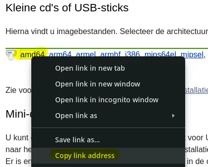
Next, paste the URL into Proxmox:
- Access local storage
- Navigate to 'ISO Images'
- Choose 'Download from URL'
- Paste the URL in the URL field
- Click 'Query URL'
- Finaly, select 'Donwload'
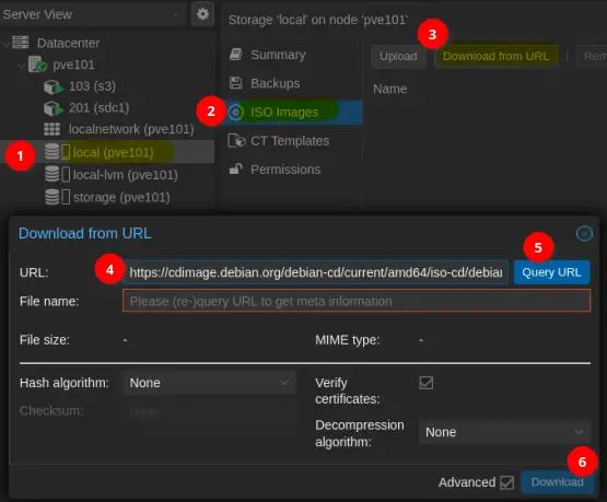
6.2.1.2. Create VM
Let's create the VM:
- Click on 'Create VM'
- General:
- VM ID: 301
- Name: file1
- Click 'Next'
- OS:
- Select ISO Image: debian-xx.y.z-amd64-netinst.iso
- Click 'Next'
- System:
- SCSI Controller: VirtIO SCSI
- Check the box 'Qemu Agent'
- Click 'Next'
- Disk:
- Storage: storage
- Disk size (GiB): e.g. 640
- Cache: Write back
- Click 'Next'
- CPU:
- Sockets: 1
- Cores: 4
- Click 'Next'
- Memory:
- Memory (MiB): 2048
- Minimum memory (MiB): 2048
- Click 'Next'
- Network:
- Bridge: vmbr0
- VLAN Tag: 16
- Model: Intel E1000 (not 'virtio'; doesn't work)
- Click 'Next'
- Confirm
- Review
- Click 'Finish'
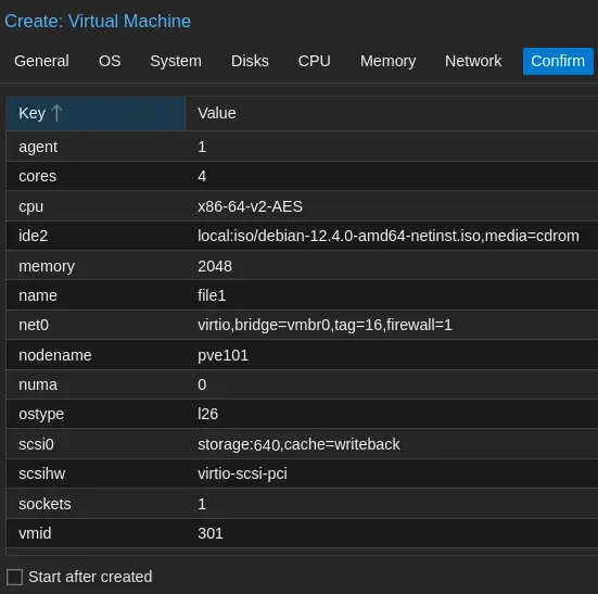
Please be partient while the VM is being created.
6.2.1.3. Install Debian from ISO
Start the VM:
- Select '301 (file1)' from the list
- Select 'Console'
- Click 'Start Now'
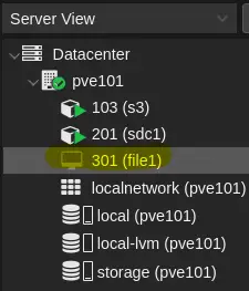
Installation process:
The assumption is that you'll press Enter to execute the steps outlined below. Explicitly stating this at each step might be excessive. Use arrow-keys and tab-key to select options.
- Debian Installer:
Select 'Install' once the Debian installer appears
- Select a language
Select the prefered language:
e.g. English - Select your location
Select the prefered country:
e.g. Other > Europe > Netherlands - Configure locales
Select system local:
e.g. United States - Configure keyboard
Select the keyboard:
e.g. American English - Configure the network
- The installer will complain the autoconfiguration failed. This is correct as DHCP is not enabled (in pfSense).
Press Enter to continue... - The default selection is 'Configure network manually'
Press Enter to continue... - IP address:
10.10.16.101/24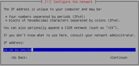
- Gateway:
- 10.10.16.1
- Name server address (mind the space):
10.10.16.201 10.10.16.1
- The installer will complain the autoconfiguration failed. This is correct as DHCP is not enabled (in pfSense).
- Hostname:
- Hostname:
file1
- Hostname:
- Domain name
- Domain name:
ad.lan.gigabitjes.nl
- Domain name:
- Set up users and Passwords
- Enter the root password:
**************** - Re-enter the root password:
**************** - Enter the full name of new user:
Maintenance User - Enter the username of the account:
main - Enter the new password for the new user:
**************** - Re-enter the same password [..]
****************
- Enter the root password:
- Partition disks
- Partitioning method:
Guided - user entire disk - Select disk partition:
SCSI [..] QEMU HARDDISK - Partitioning Scheme:
All files in one partition [..] - Overview:
Finish partitioning and write changes to disk - Write changes to disk?
Yes
- Partitioning method:
- Configure package manager
- Scan extra installation media?
No - Select mirror
E.g. 'Netherlands' - Debian Archive mirror:
E.g. 'deb.debian.org' or one of the other available options - HTTP Proxy information
Just press Enter
- Scan extra installation media?
- Configuring popularity-contest
- Participate in the package usage survey?
No
- Participate in the package usage survey?
- Software selection
- Deselect: Debian desktop environment
- Deselect: GNOME
- Select: SSH server
- Keep selected: standard system utilities

- Configuring grub-pc
- Install the GRUB boot loader to your primary drive?
Yes - Device for boot loader installation:
/dev/sda (scsi-QEMU [..])
- Install the GRUB boot loader to your primary drive?
- Finishing installation
- Please chose <Continue> to reboot
Press Enter
- Please chose <Continue> to reboot
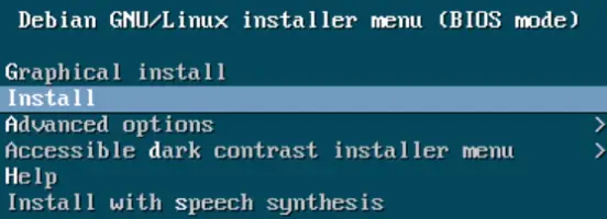

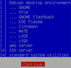
The VM will reboot. Let's continue with the followig section.
6.2.2. Configure Debian
We will executed commands both as user and as root. Every command starting with a "$" will be in user mode. Every command starting with "#" is executed as root.
6.2.2.1. Login
Use SSH to login to the fileserver. From a Linux terminal you can easily connect with fhe following command:
$ ssh [email protected]
Alternativly use PuTTY or login via the Console in Proxmox.
Accept the fingerprint when requested.
6.2.2.2. Add user to sudoers list
We will add the user main to the sudoers list.
First we'll install `sudo`:
- $ su -
- Enter the root password
- # apt update
- # apt install sudo
Now we are ready to add the user to the suoers group:
- # adduser main sudo
- # exit; exit
With the command `exit; exit` we'll logout. It will end both root and main's SSH session.
Login again and test if sudo works:
- $ ssh [email protected]
- $ sudo su
- Enter the password of user main to elevate
6.2.2.3. Verify and correct settings
Check the hostname, both with and without prefix:
# hostname && hostname -f
Result:
file1
file1.ad.lan.gigabitjes.nl
Verify the IPv4 address:
# ip a
Result:
[..]
2: ens18: <BROADCAST,MULTICAST,UP,LOWER_UP> mtu 1500 qdisc fq_codel state UP group default qlen 1000
 link/ether bc:24:11:10:15:34 brd ff:ff:ff:ff:ff:ff
 altname enp0s18
 inet 10.10.16.101/24 brd 10.10.16.255 scope global ens18
[..]
Verify DNS resolving:
# cat /etc/resolv.conf
Result:
search ad.lan.gigabitjes.nl
nameserver 10.10.16.201
nameserver 10.10.16.1
Note: The first nameserver IPv4 relates to the domain controller. The second nameserver IPv4 relates to the DNS resolver running on the firewall.
Verify and correct swappiness:
# cat /proc/sys/vm/swappiness
Result:
60
Change this to something sensible:
# echo 10 > /proc/sys/vm/swappiness
# sysctl -p
# cat /proc/sys/vm/swappiness
Result:
10
Store the settings to file:
# echo "vm.swappiness=10" >> /etc/sysctl.d/80-sysctl-swappiness.conf
Note: The file 80-sysctl-swappiness.conf will be applied during boot time.
6.2.2.4. NTP
Time management is crucial. The default NTP service is systemd-timesyncd. Let's swiftly configure systemd-timesyncd for our file server.
- Even though systemd-timesyncd is already installed, it won't hurt to run the installation command:
apt -y install systemd-timesyncd - Now, let's edit timesyncd.conf:
nano /etc/systemd/timesyncd.conf - Uncomment the lines for NTP and FallbackNTP, and set the NTP server to 10.10.16.1.
NTP=10.10.16.1
FallbackNTP=0.debian.pool.ntp.org 1.debian.pool.ntp.org 2.debian.pool.ntp.org 3.debian.pool.ntp.org
- Verify the configuration:
timedatectl show-timesync --al
- Enable and start systemd-timesyncd:
timedatectl set-ntp true
- For good measure, forcibly enable and restart systemd-timesyncd:
systemctl enable systemd-timesyncd
systemctl restart systemd-timesyncd
- Check the status:
systemctl startus systemd-timesyncd
- And the synchronization status:
timedatectl timesync-status
This ensures that our file server is well-synchronized with the network time.
6.2.3. Install and configure Samba Fileserver
You'll probably still running commands as root. Enter `exit` to revert back to usermode:
# exit
Install required packages:
$ sudo apt update && sudo apt -y install acl samba winbind libnss-winbind krb5-user
Configure Kerberos:
$ sudo mv /etc/krb5.conf /etc/krb5.conf.bak
$ sudo nano /etc/krb5.conf
Add the following lines and save changes:
[libdefaults]
 default_realm = AD.LAN.GIGABITJES.NL
 dns_lookup_realm = false
 dns_lookup_kdc = true
Configure NSS:
$ sudo nano /etc/nsswitch.conf
Change the following lines and save changes:
passwd: files winbind
group: files winbind
hosts: files dns wins
Configure Samba:
$ sudo mv /etc/samba/smb.conf /etc/samba/smb.conf.bak
$ sudo nano /etc/samba/smb.conf
Add the following lines and save changes:
# Global parameters
[global]
 dedicated keytab file = /etc/krb5.keytab
 kerberos method = secrets and keytab
 realm = AD.LAN.GIGABITJES.NL
 security = ADS
 server role = member server
 winbind refresh tickets = Yes
 workgroup = AD
 idmap config * : backend = tdb
 idmap config * : range = 3000-7999
 idmap config ad : backend = rid
 idmap config ad : range = 10000 - 999999
 map acl inherit = Yes
 vfs objects = acl_xattr
Check Kerberos (1):
$ sudo kinit administrator
Result (output may vary):
Password for [email protected]:
Warning: Your password will expire in 32 days on Sun 18 Feb 2024 10:00:50 PM CET
Check Kerberos (2):
$ sudo klist
Result (output may vary):
Ticket cache: FILE:/tmp/krb5cc_0
Default principal: [email protected]

Valid starting Expires Service principal
01/17/2024 21:37:46 01/18/2024 07:37:46 krbtgt/[email protected]
 renew until 01/18/2024 21:37:42
Verify the Samba configuration
$ sudo testparm
Result:
Load smb config files from /etc/samba/smb.conf
Loaded services file OK.
Weak crypto is allowed by GnuTLS (e.g. NTLM as a compatibility fallback)
Server role: ROLE_DOMAIN_MEMBER
Press enter to see a dump of your service definitions
# Global parameters
[global]
 dedicated keytab file = /etc/krb5.keytab
 kerberos method = secrets and keytab
 realm = AD.LAN.GIGABITJES.NL
 security = ADS
 winbind refresh tickets = Yes
 workgroup = AD
 idmap config * : range = 3000-7999
 idmap config ad : backend = rid
 idmap config ad : range = 10000 - 999999
 idmap config * : backend = tdb
 map acl inherit = Yes
 vfs objects = acl_xattr
Join the domain
$ sudo /usr/bin/samba-tool domain join ad.lan.gigabitjes.nl MEMBER -U administrator
Result (output may vary):
Password for [AD\administrator]:
Joined domain ad.lan.gigabitjes.nl (S-1-5-21-1971466082-2551851020-532596661)
Restart services and make sure these are being started during system boot:
$ sudo systemctl restart smbd nmbd winbind
$ sudo systemctl enable smbd nmbd winbind
Result:
Synchronizing state of smbd.service with SysV service script with /lib/systemd/systemd-sysv-install.
Executing: /lib/systemd/systemd-sysv-install enable smbd
Synchronizing state of nmbd.service with SysV service script with /lib/systemd/systemd-sysv-install.
Executing: /lib/systemd/systemd-sysv-install enable nmbd
Synchronizing state of winbind.service with SysV service script with /lib/systemd/systemd-sysv-install.
Executing: /lib/systemd/systemd-sysv-install enable winbind
We are pleased to announce that our file server has been successfully integrated into the domain.
6.2.4. Set up shares
It's time to set up a file share.
First we'll prepare a folder:
$ sudo mkdir -p /srv/samba/data
$ sudo chmod -R 775 /srv/samba/data
$ sudo chown -R "AD\administrator":root /srv/samba/data
The latter command will only work when the configuration is correct. The user administrator is a domain member.
Edit the smb.conf file to add the share:
$ sudo nano /etc/samba/smb.conf
Add the following to the end of the file and save changes:
[Data]
 acl_xattr:ignore system acl = Yes
 acl allow execute always = Yes
 acl group control = Yes
 inherit acls = Yes
 inherit owner = windows and unix
 inherit permissions = Yes
 path = /srv/samba/data
 read only = No
It's a good practice to enable access-based share enumeration. This prevents users without read or write access from viewing files and folders.
Add the following line to the [global] settings. It's fine to be added at the end of the section:
access based share enum = yes
Now, test the changes:
sudo testparm
Result:
Load smb config files from /etc/samba/smb.conf
Loaded services file OK.
Weak crypto is allowed by GnuTLS (e.g. NTLM as a compatibility fallback)
Server role: ROLE_DOMAIN_MEMBER
Press enter to see a dump of your service definitions
# Global parameters
[global]
 dedicated keytab file = /etc/krb5.keytab
 kerberos method = secrets and keytab
 realm = AD.LAN.GIGABITJES.NL
 security = ADS
 server role = member server
 winbind refresh tickets = Yes
 workgroup = AD
 idmap config ad : range = 10000 - 999999
 idmap config ad : backend = rid
 idmap config * : range = 3000-7999
 idmap config * : backend = tdb
 access based share enum = Yes
 map acl inherit = Yes
 vfs objects = acl_xattr

[Data]
 acl allow execute always = Yes
 acl group control = Yes
 inherit acls = Yes
 inherit owner = windows and unix
 inherit permissions = Yes
 path = /srv/samba/data
 read only = No
 acl_xattr:ignore system acl = Yes
Restart the services
$ sudo systemctl restart smbd nmbd winbind
The subsequent procedure involves logging into a Windows computer integrated into the domain as an Administrator. In this step, we will create folders and incorporate domain groups or domain users to facilitate access. A comprehensive exploration of this process will be undertaken in the forthcoming chapter.
7. Managing Users and Computers
Within our network, both users and computers play essential roles.
7.1. Administrative Windows VM
To start, we need to introduce a Windows computer designated for administrative purposes. This particular machine will be specifically dedicated to administration tasks.
As part of this setup, we will initiate a virtual machine running Windows 11 Pro. Moreover, you have the flexibility to connect a Windows computer directly to the switch as an alternative approach.
7.1.1. Obtain installation media
Acquiring the installation media for Windows Pro is a straightforward process. The media can be obtained from https://www.microsoft.com/software-download/windows11. Navigate to the site, scroll down, and choose the download option. Specifically, select "Windows 11 (multi-edition ISO for x64 devices)" and click 'Download Now'. Proceed to choose your preferred language and click 'Confirm'.
Do not initiate the download by clicking the '64-bit download' button; instead, opt for an alternative method, right-click, and select 'Copy link address'.
Now, within Proxmox, designate the storage and access 'ISO images'. Opt for 'Download from URL', paste the copied URL into the 'URL' field, and then click 'Query URL'. Finally, initiate the download by clicking 'Download'. This will commence the download process.
7.1.2. VirtIO Drivers
We'll use virtual devices which require drivers. Right-click the following link and choose 'Download from URL':
https://fedorapeople.org/groups/virt/virtio-win/direct-downloads/stable-virtio/virtio-win.iso
Now, within Proxmox, designate the storage and access 'ISO images'. Opt for 'Download from URL', paste the copied URL into the 'URL' field, and then click 'Query URL'. Finally, initiate the download by clicking 'Download'. This will commence the download process.
7.1.3. Create VM
It's time to create the VM for Windows in Proxmox:
- Click 'Create VM'
- General:
- VM ID: 901
- Name: wadm1
- Next
- OS:
- ISO image: Win11_23H2_English_x64v2.iso
- Type: Microsoft Windows
- Version: 11/2022
- Check the option 'Add additional drive for VirtIO drivers'
- ISO image: virtio-win.iso
- Next
- System
- Graphic card:
- Select 'SPICE' if you like to use the Virtual Machine Viewer.
- Select 'Default' if you just want to use the default Proxmox console.
- Machine: q35
- BIOS: OVMF (UEFI)
- EFI Storage: storage
- SCSI Controller: VirtIO SCSI
- Check option 'Qemu Agent'
- TPM Storage: storage
- Next
- Graphic card:
- Disks
- Storage: storage
- Disk size (GiB): e.g. "200"
- Cache: Write back
- Next
- CPU
- Sockets: e.g. "1"
- Cores: e.g. "4"
- Next
- Memory
- Memory (GiB): e.g. 8192
- Next
- Network
- Bridge: vmbr0
- VLAN Tag: we will not enter a tag, as we want to run this VM in the management VLAN
- Model: VirtIO (paravirtualized)
- Next
- Confirm
- Review settings and click 'Finish'
- Wait until the VM is created
7.1.4. Install Windows 11 Pro
Click 'Start Now' to initiate the VM. Quickly click the Console screen and press a key when prompted to boot from CD/DVD.
If 'SPICE' is selected as the Graphic card, the mouse cursor may be out of focus. To address this, click the small down arrow next to '>_ Console' in the upper right corner of the screen. Now, click 'Spice'. Next, open the file in Virtual Machine Viewer.
Please note: Press 'ALT' + 'CTRL' + 'R' to release the mouse cursor from Virtual Machine Manager.
Now, proceed with the Windows installation as usual. Load the storage driver for the VirtIO SCSI Controller.
- Enter the language and other preferences and click 'Next' to continue.
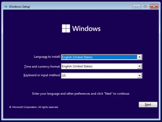
- Click 'Install now'.
- Click 'I don't have a product key' when requested to enter the product key.
- Select 'Windows 11 Pro' and click Next.
- Accept the license and click 'Next'.
- Click 'Custom: Install Windows only (advanced).
- Click 'Load driver' to load the storage driver. Next click 'OK'. Select 'Red Hat VirtIO SCSI pass-through controller (D:\amd64\w11\vioscsi.info) and cick 'Next'.
- Click Next to allocated the space.
- Windows will install and will reboot once completed.


Windows will start the Out of Box Experience:
- Press 'Shift' + 'F10' to open a command prompt
Note: This key combination works in both Proxmox's web console (noVNC) and Virtual Machine Viewer.
Alternatively, press 'Win-key' + 'R' and run 'CMD' via the Run dialog. - Enter the following command and press Enter:
oobe\BypassNRO.cmd
Windows will reboot and continue the Out of Box Experience.
This enables setting up Windows without an internet connection. - Select the country or region and click 'Yes'
- Select the keyboard layout and click 'Yes'
- Click 'Add layout' to add a second keybouard layout. The default selection is 'Skip'.
- Click 'I don't have internet'
- Click 'Continue with limited setup'
- Enter a name when asked who's going to use this device:
E.g. 'LocalAdmin' - Click Next
- Enter a password and click 'Next'; or alternativly just click 'Next and set a password later.
- Answer the questions (Yes/No; Accept, et cetera).
Windows will continue and inform you about the progress. The result should be something similar to the below screenshot.
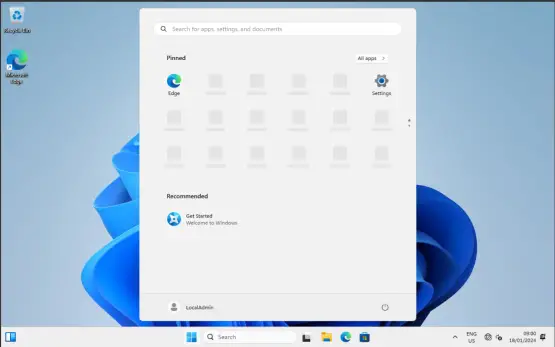
Now, install the VirtIO drivers by starting 'virtio-win-guest-tools' from the virtio-win CD:
- Agree to the license terms and click 'Install'.
- Click 'Yes'
- Click 'Next'
- Accept the agreement and click 'Next'
- Follow on-screen instruction (basicly clicking next...)
The result is a flawlessly running Windows 11 Pro installation.
Once the VirtIO drivers are installed, the screen resolution should improve, and network connectivity should work.
Verify network connectivity by looking at the network icon in the lower right corner of the screen. Alternatively, open the Command Prompt and query the IP configuration with the 'ipconfig /all' command.
C:\>ipconfig /all
Windows IP Configuration

Host Name . . . . . . . . . . . .  : DESKTOP-J6P9KU3
 Primary Dns Suffix . . . . . . .  :
 Node Type . . . . . . . . . . . . : Hybrid
 IP Routing Enabled. . . . . . . . : No
 WINS Proxy Enabled. . . . . . . . : No
 DNS Suffix Search List. . . . . . : lan.gigabitjes.nl

Ethernet adapter Ethernet:

 Connection-specific DNS Suffix .  : ad.lan.gigabitjes.nl
 Description . . . . . . . . . . . : Red Hat VirtIO Ethernet Adapter
 Physical Address. . . . . . . . . : BC-24-11-3F-BA-6F
 DHCP Enabled. . . . . . . . . . . : Yes
 Autoconfiguration Enabled . . . . : Yes
 Link-local IPv6 Address . . . . . : fe80::3846:3c84:5c40:3d1a%20(Preferred)
 IPv4 Address. . . . . . . . . . . : 172.21.1.204(Preferred)
 Subnet Mask . . . . . . . . . . . : 255.255.255.0
 Lease Obtained. . . . . . . . . . : Thursday, 18 January 2024 09:05:25
 Lease Expires . . . . . . . . . . : Thursday, 18 January 2024 11:05:25
 Default Gateway . . . . . . . . . : fe80::20d:b9ff:fe48:3c89%20
                                     172.21.1.1
 DHCP Server . . . . . . . . . . . : 172.21.1.1
 DHCPv6 IAID . . . . . . . . . . . : 347874321
 DHCPv6 Client DUID. . . . . . . . : 00-01-00-01-2D-3A-94-1D-BC-24-11-3F-BA-6F
 DNS Servers . . . . . . . . . . . : 172.21.1.1
 NetBIOS over Tcpip. . . . . . . . : Enabled
 Connection-specific DNS Suffix Search List :
                                     lan.gigabitjes.nl
7.1.5. Remote Server Administration Tools (RSAT)
To manage Users and Computers and set Group Policies for our domain, we'll use PowerShell to add Windows Capabilities.
Start PowerShell as Administrator and look up the required tools:
Get-WindowsCapability -Name RSAT* -Online | Select-Object -Property DisplayName, Name, State
Install these two tools:
Add-WindowsCapability -Online -Name "Rsat.ActiveDirectory.DS-LDS.Tools~~~~0.0.1.0"
Add-WindowsCapability -Online -Name "Rsat.GroupPolicy.Management.Tools~~~~0.0.1.0"
Now, proceed to join the Windows VM to AD.
7.1.6. Domain Join
Ensuring a local admin account is in place is a prudent step, especially in the event of a trust relationship failure between the workstation and the domain. Proceed by setting a password for the LocalAdmin user account.
7.1.6.1. Local Admin Account
Press 'CTRL' + 'ALT' + 'DELETE' within the VM. This can be executed through the on-screen buttons in noVNC or the button-menu in Virtual Machine Viewer.
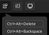
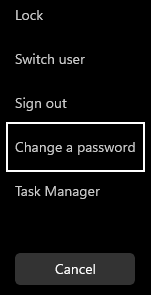
Next, click 'Change a password'.
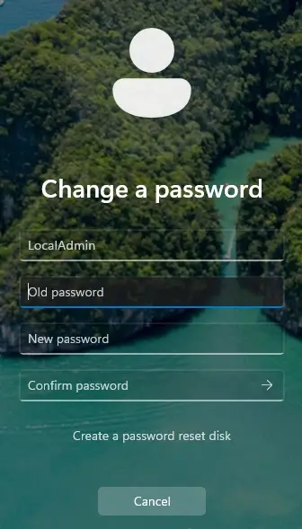
Simply skip the 'Old password' if no password is set. Enter and confirm the new password.
7.1.6.2. Join computer to domain
Press <Win-key> + <R> and open System Properties:
sysdm.cpl
Click 'Change...' in the 'Computer Name' tab.
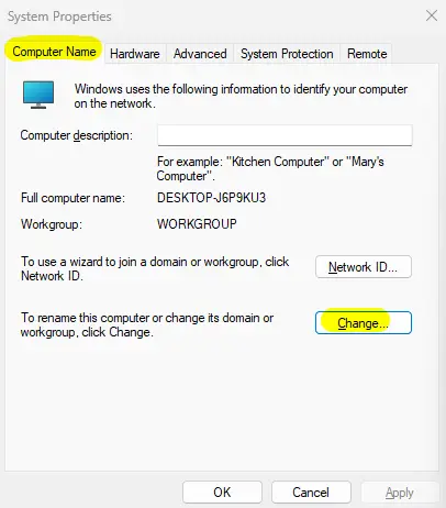
Enter the desired computer name (e.g., WS01). Check the 'Domain' radio button and input the domain name. Finally, click 'OK'.
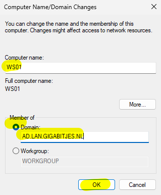
Enter the domain administrator's username and password (default: 'Administrator' with the password set during domain provisioning).
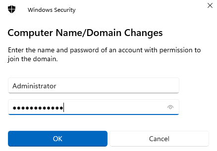
Follow the on-screen instructions.
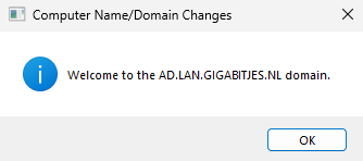
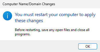
Click 'Close' and 'Restart Now'.
After the computer restarts, click 'Other user' in the lower-left corner of the screen. Log in with the domain administrator's account and password.
A caveat is necessary when logging in with the username 'Administrator'; prepend the NetBIOS name of the domain to the username, separated by a backslash (e.g., "AD\Administrator"). Alternatively, enter the username followed by the FQDN of the domain, separated by an at-sign (e.g., "[email protected]").
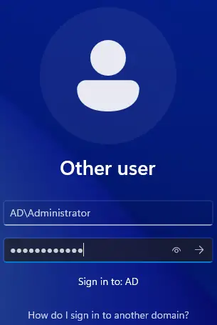
7.1.7. Using Remote Server Administration Tools (RSAT)
Access the following tools through either 'Windows Tools' or 'Server Manager,' both conveniently located in the start menu.
7.1.7.1. Overview
Our focus centers on these tools:
- Active Directory Users and Computers
dsa.msc - ADSI Edit
adsiedit.msc - Group Policy Management
gpmsc.msc
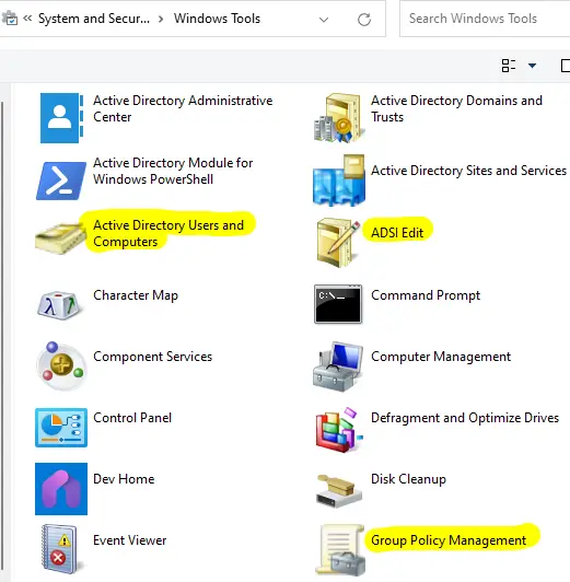
Pin these tools to Start or the Taskbar, or simply drag them to the desktop.
7.1.7.2. Active Directory Users and Computers (ADUC)
'Active Directory Users and Computers' is a management tool within the Windows operating system that allows administrators to perform tasks related to user accounts, groups, and computer objects in an Active Directory environment. It provides a graphical interface for managing and organizing these directory objects, enabling administrators to create, modify, and delete user accounts, reset passwords, manage group memberships, and organize computer objects within organizational units (OUs). This tool is crucial for maintaining the structure and security of an Active Directory domain.
When using 'Active Directory Users and Computers,' ensure 'Advanced Features' are enabled via 'View' > 'Advanced Features'. Note that there's a bug that may initially crash the tool. Close and reopen 'Active Directory Users and Computers,' then re-enable 'Advanced Features'.
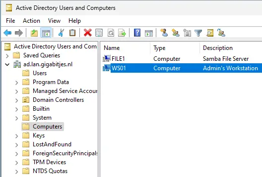
While creating computer accounts in advance is optional (as a computer account is created during domain join), user accounts can be easily generated through the context-menu. Right-click 'Users' and select 'New' > 'User.'
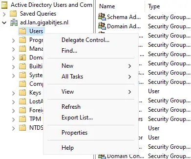
For organizational clarity, consider creating new Organizational Units (OUs). For example, in my home office, I might establish an OU named 'Nova' and nest additional OUs for Users, Groups, and Computers.
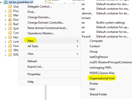
Subsequently, move 'WS01' to the newly created 'Computers' OU under 'Nova' and the Samba file server 'FILE1' to the 'Servers' OU.
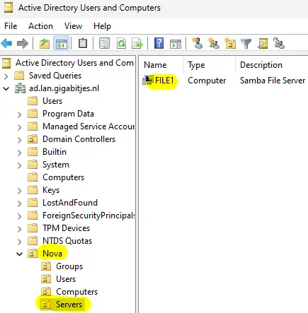
An effective practice is creating access groups within the 'Groups' OU. For instance, establish 'GRP_FSS_Public' to grant access to public folders on the file server.
Critical Note: Never relocate a domain controller to another Organizational Unit (OU)! Always retain it within the default 'Domain Controllers' OU. Microsoft strongly discourages moving domain controllers from this standard OU, as doing so can jeopardize proper operation and is not recommended.
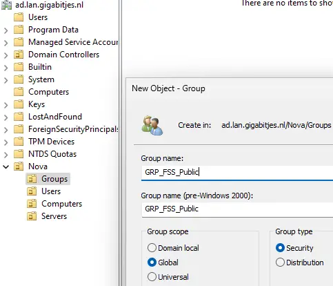
The next step involves creating user accounts and organizing group memberships.
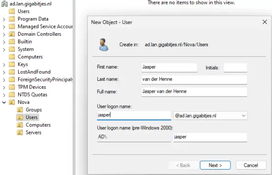
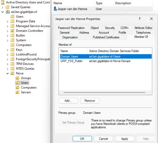
7.1.7.3. ADSI Edit
ADSI Edit is a powerful tool designed for advanced users and administrators who need to make low-level modifications to the Active Directory. Due to its potential impact on the system, it should be used cautiously, and changes should be made only by those with a deep understanding of Active Directory structure and operations.
If you encounter a situation where the display name of a renamed computer doesn't reflect the new name in Active Directory Users and Computers (ADUC), you might use ADSI Edit to correct it.
7.1.7.4. Group Policy Management
'Group Policy Management' is a Windows administrative tool designed for configuring and managing Group Policy settings in an Active Directory environment. It allows administrators to define and enforce security policies, system settings, and user configurations across a network of Windows-based computers. With Group Policy Management, administrators can create, edit, and organize Group Policy Objects (GPOs), which are sets of policies that can be applied to specific users, groups, or computer accounts. This tool provides centralized control over various aspects of the Windows operating system, ensuring consistent and secure settings across an organization's network.
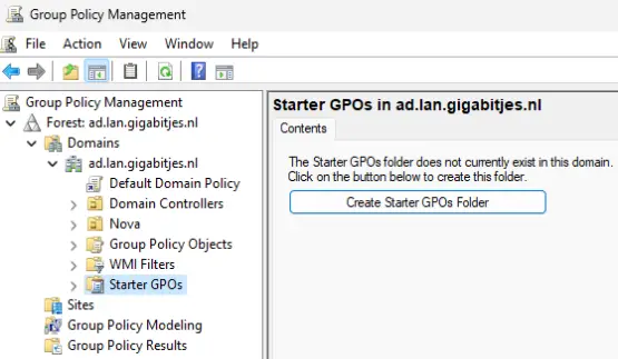
Establish the Starter GPOs Folder and proceed to add Group Policy Objects (GPOs) as needed. It is recommended to create individual GPOs for each policy element rather than consolidating everything under 'Default Domain Policy,' as this approach promotes better organization and management practices.
While it's possible to create a Group Policy Object (GPO) directly within an Organizational Unit (OU), it is recommended to initially create it within the 'Group Policy Objects' container. Subsequently, link the GPO to the desired OU for proper configuration and management.
Additionally, adopting a structured naming convention for Group Policy Objects (GPOs) is recommended. A well-defined naming convention allows administrators to easily discern the purpose and target (computers or users) of a GPO from its name.
For general drive mappings, consider using a GPO named 'UserDriveMappings_General.
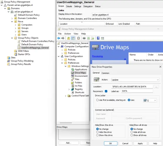
Linking a Group Policy Object (GPO) is a straightforward process of dragging and dropping the item. While this method is effective, it becomes less practical as the list grows longer. In such instances, it is recommended to link a GPO using the context menu, where the option 'Link an existing GPO...' can be selected for more efficient management.
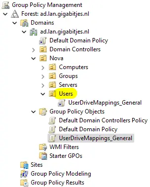
8. File sharing
In a previous step, we established a DATA share on our file server and implemented a policy to map this share to drive letter Q, enhancing user convenience. However, a deliberate limitation has been introduced: users are currently restricted from creating files and folders. This limitation is not a technical issue but rather a design choice. The intended approach is to manually create the primary folders within our share and configure the necessary access rights for our users.
On our administrative workstation, we'll navigate to \file1.ad.lan.gigabitjes.nl\data and create a folder named 'General'. Subsequently, we'll access 'Properties' from the context-menu for the new folder.
Now, we open the 'Security' tab and click 'Advanced'.
The initial task involves 'Disabling inheritance', wherein inherited permissions are converted into explicit permissions without removal.
Next, we'll exclude 'Everyone' from the permission list and substitute it with 'GRP_FSS_Public'. Applying permissions to 'This folder only,' we select specific basic permissions:
- Read & Execute
- List folder contents
- Read
- Write
- This configuration prohibits users from deleting the folder.
Following this, we click 'Add' once more, applying permissions to subfolders and files exclusively. We select 'Full control' and implement the settings.
To verify the adjustments, we switch to the previously created user. The user can create files and folders within the 'General' directory but is restricted from renaming, deleting, or moving the folder. However, the user possesses full control over the contents within the folder.
9. Connectiong workstations
In the preceding sections, we utilized a workstation directly linked to the management VLAN. When connecting a user's workstation, it is directed to the office VLAN (32). However, connecting to the domain controller from this network is currently impossible due to the absence of fundamental firewall rules. In addition to these internal services, we would like to establish direct connections to the mail and web servers.
Now, let's establish firewall rules to facilitate workstation registration on the domain, allowing users to commence their tasks seamlessly.
We will utilize our VLAN overview along with a list of our server IP addresses and the corresponding ports that need to be included in our firewall rules for multiple servers.
9.1. Overviews
We will utilize our VLAN overview along with a list of our server IP addresses and the corresponding ports that need to be included in our firewall rules for multiple servers.
9.1.1. VLAN Overview
| Interface | VLAN tag | Priority | Name | Subnet | Gateway | Description | Examples |
|---|---|---|---|---|---|---|---|
| igb1 (lan) | 1 | - | L1_0001_MNG1 | 172.21.1.0/24 | 172.21.1.1 | Management 1 | Switches, access points |
| igb1 (lan) | 2 | - | L1_0002_MNG2 | 172.22.2.0/24 | 172.22.2.1 | Management 2 | Hypervisor(s), KVM-over-IP |
| igb1 (lan) | 16 | - | L1_0016_SRVS | 10.10.16.0/24 | 10.10.16.1 | Server VMs | Server VMs |
| igb1 (lan) | 18 | - | L1_0018_STOR | 10.10.18.0/24 | 10.10.18.1 | Storage | Network Attached Storage (NAS) |
| igb1 (lan) | 32 | - | L1_0032_OFF1 | 10.10.32.0/24 | 10.10.32.1 | Workstations | Desktop and laptop computers |
| igb1 (lan) | 36 | - | L1_0036_PRNT | 10.10.36.0/24 | 10.10.36.1 | Peripherals | Printers |
| igb1 (lan) | 251 | - | L1_0251_IOTD | 172.31.251.0/24 | 172.31.251.1 | Internet of Things | Solar panel inverters |
| igb1 (lan) | 252 | - | L1_0252_DMZ1 | 172.31.252.0/24 | 172.31.252.1 | DMZ | Web and mail server |
| igb1 (lan) | 253 | - | L1_0253_GNET | 172.31.253.0/24 | 172.32.253.1 | Guest Network | Guest Wi-Fi network |
9.1.2. Server IP addresses
| Servername | VLAN | LAN IP | WAN IP | Description |
|---|---|---|---|---|
| 103 s3.gigabitjes.nl | 252 | 172.31.252.103 | 217.nnn.nnn.27 | ISPConfig Mail and Web Server |
| 201 sdc1.ad.lan.gigabitjes.nl | 16 | 10.10.16.201 | - | Domain Controller |
| 301 file1.ad.lan.gigabitjes.nl | 16 | 10.10.16.101 | - | File Server |
9.1.3. Admin Computer
| Servername | VLAN | LAN IP | WAN IP | Description |
|---|---|---|---|---|
| 901 ws01.ad.lan.gigabitjes.nl | 16 | 172.21.1.{...} | N/A | Admin computers, DHCP, in management VLAN |
9.1.4. Ports
| Port | Protocol | Purpose | Server | Description |
|---|---|---|---|---|
| 53 | TCP | DNS over TCP | Domain Controller | DNS data exceeding 512 bytes |
| 88 | TCP | Kerbores | Domain Controller | |
| 135 | TCP | End Point Mapper | Domain Controller, File Server | |
| 139 | TCP | NetBIOS Session | Domain Controller, File Server | |
| 445 | TCP | SMB | Domain Controller, File Server | |
| 464 | TCP | Kerberos kpasswd | Domain Controller | |
| 636 | TCP | LDAPS | Domain Controller | |
| 3268 | TCP | Global Catalog | Domain Controller | |
| 3269 | TCP | Global Catalog SSL | Domain Controller | |
| 49152:65535 | TCP | Dynamic RPC Ports | Domain Controller | |
| 53 | UDP | DNS over UDP | Domain Controller | |
| 88 | UDP | Kerberos | Domain Controller | |
| 123 | UDP | NTP | Domain Controller | |
| 137 | UDP | NetBIOS Name Service | Domain Controller, File Server | |
| 138 | UDP | NetBIOS Datagram | Domain Controller, File Server | |
| 389 | UDP | LDAP | Domain Controller | |
| 464 | UDP | Kerberos kpasswd | Domain Controller |
TCP Ports 135, 139, 445 + UDP 137, 138 will be used by the file server.
To enhance printing efficiency, please make sure to open the TCP port range 49152:65535 when printers are served. This ensures smooth and prompt print job processing, eliminating any potential delays (30-45 seconds).
Kindly refrain from sharing printers via DNS in mixed environments, especially when utilizing a non-Windows DHCP server. Instead, opt for using the IP address of the printer-sharing server.
To access the mail and web services, we have to open the following ports.
| Port | Protocol | Purpose | Server | Description |
|---|---|---|---|---|
| 25 | TCP | SMTP | ISPConfig | Debatable |
| 143 | TCP | IMAP | ISPConfig | |
| 465 | TCP | SMTPS | ISPConfig | |
| 587 | TCP | MSA | ISPConfig | |
| 993 | TCP | IMAPS | ISPConfig | |
| 80 | TCP | HTTP | ISPConfig | |
| 443 | TCP | HTTPS | ISPConfig |
It's advisable to organize the ports into port aliases and then construct the firewall rules in pfSense.
9.2. Firewall Rules
Refer to paragraph 3.3.1 for the steps to create firewall aliases and rules.
Open the web interface of pfSense and navigate to "Firewall" > "Aliases" > "Ports".
Add the port aliasses and add the ports as stated above:
- Ports_DC_TCP (Ports, Domain Controller, TCP)
- Ports_DC_UDP (Ports, Domain Controller, UDP)
- Ports_FS_TCP (Ports, File Server, TCP)
- Ports_FS_UDP (Ports, File Server, UDP)
- Ports_ISPC_TCP (Ports, ISPConfig, TCP)
Note: you can simply copy 'Port_Ingress_GRE_TCP' to 'Ports_ISPC_TCP'.
Result:
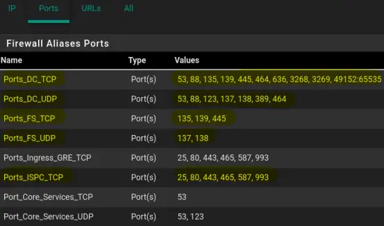
Next, add the following IP aliasses:
- IP_SDCs
- IP_FILE1
- IP_ISPC_LOCAL
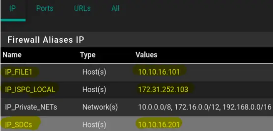
Finally create the firewall rules utilizing the aliasses on interface L1_0032_OFF1:
- Allow TCP Traffic to Domain Controllers
- Allow UDP Traffic to Domain Controllers
- Allow TCP Traffic to File Server #1
- Allow UDP Traffic to File Server #1
- Allow TCP Traffic to ISPConfig Server
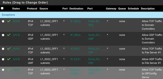
Please click here for a full screenshot of all rules for the Office LAN.
10. Conclusion
As we conclude this article, it's evident that our network, while functional, remains a bit rudimentary. There's ample room for enhancement, from introducing a second domain controller and exploring additional switch variants to replicating the firewall configuration in OPNsense, integrating mailboxes, refining workstation configurations, and, lest we forget, expanding our Active Directory policies.
I welcome your valuable feedback, and the plan is to incorporate it into the next revision of this article. Remember, I'm not navigating this journey alone; the HowtoForge community is a collaborative space where we can support each other. Feel free to share your thoughts, leave comments, or initiate discussions on the forum. Until next time! Cheers, Bouke

