Blender Shader Contour Maps
For a few years now I’ve admired contour lines. Used topographic maps they cleanly show 3D terrain in 2D space. The idea is to draw a line at certain height intervals: 0ft, 10ft, 20ft, etc, to outline the 3D space. Not only are they useful, but I think they look amazing. I wanted to create some, and I figure out how in Blender.
First attempts
Unsurprisingly, there are techniques and software out there to do this. The Geospatial Data Abstraction Library (or GDAL) has a tool called gdal_contour that can take a raster height data from the space shuttle and create vector lines from them. This uses the marching squares algorithm which more-or-less samples small squares of the height data and creates a dense polygon tracing a height level. d3’s contour library uses this too. It can create some surprisingly good looking maps! However, it does create some not great looking jagged lines if you don’t sample small enough portions.
There’s also the conrec algorithm which seems pretty similar to marching squares but uses triangles instead of squares. It seems cool and I’m not sure what software might use it.
But then I wondered if I could make this in Blender.
Turns Out, Yes
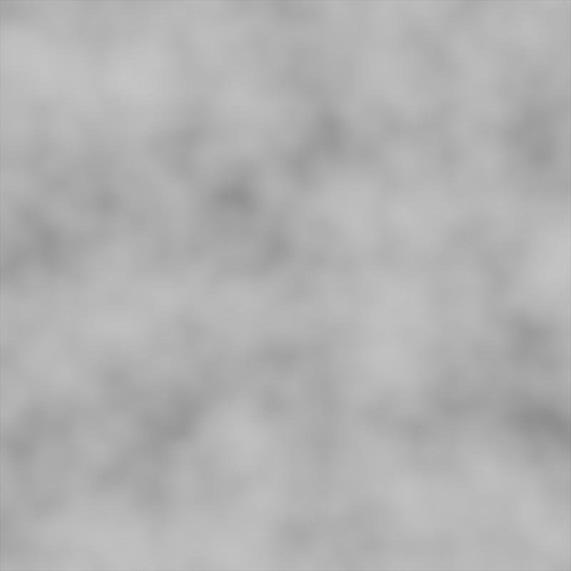
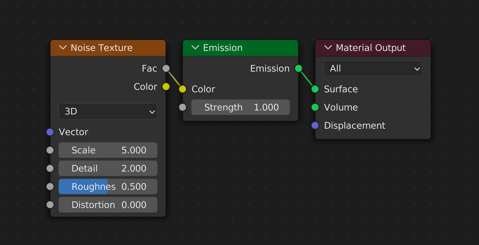
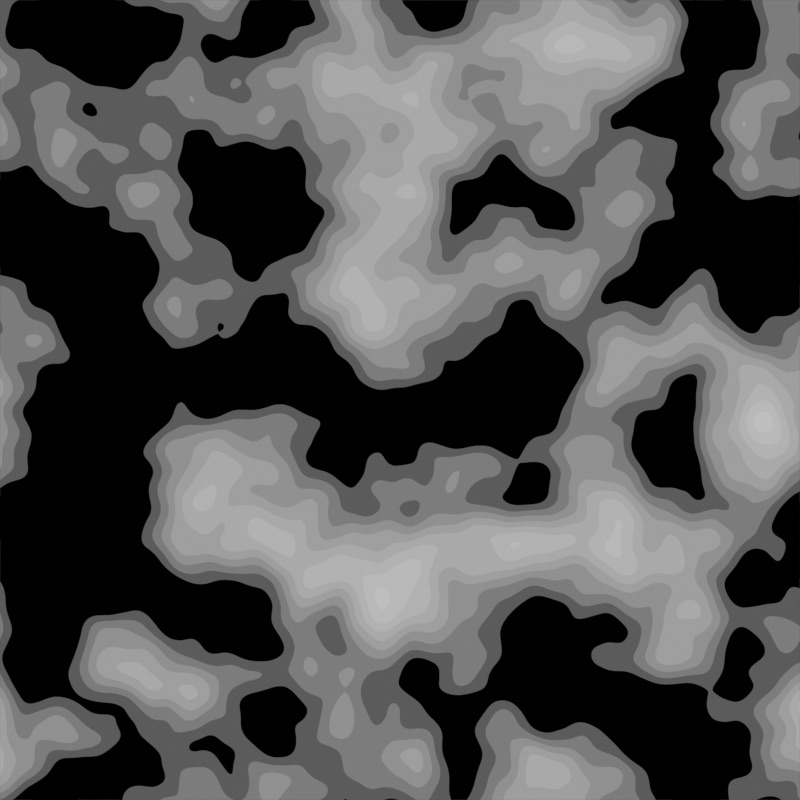
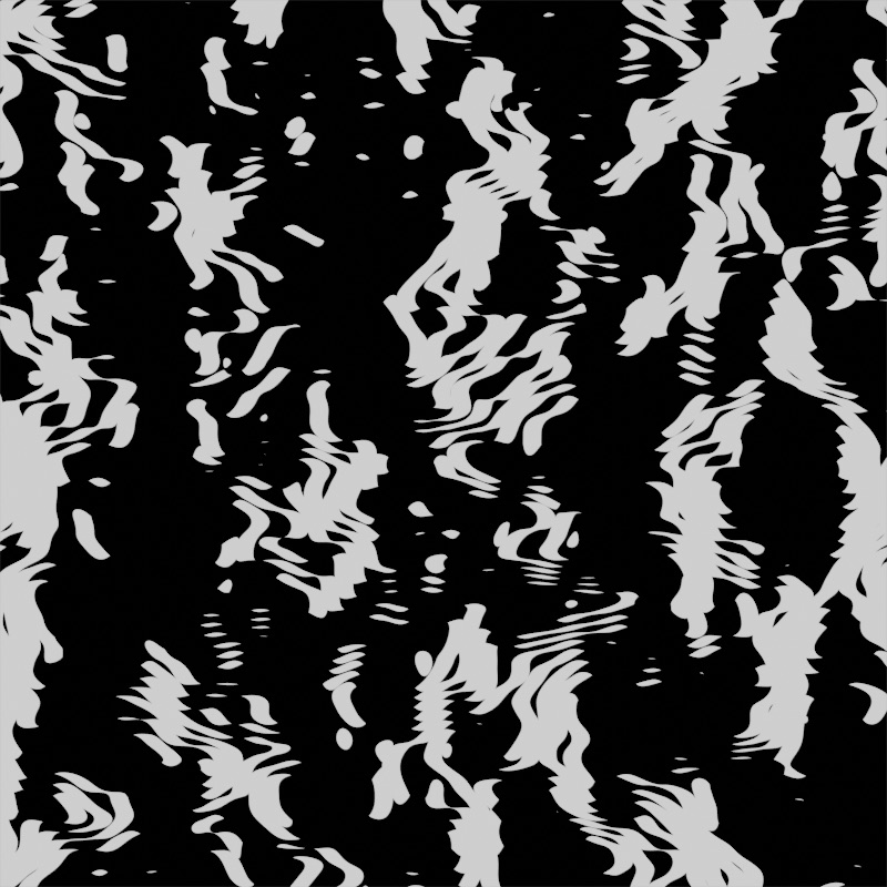
Specifically, I was wondering if I could create contour lines in Blender’s shader node editor. Making a height map is easy enough. The Noise Texture node creates Gradient noise which looks like mildly interesting terrain, if not a bit repetitive. It creates random points between 0 and 1 and smooths them to make this:
We can take take the noise and make it look a bit more like terrain:
- Set it to use 2D noise since the Z-axis we care about is the noise’s value
- Multiply it to make the range larger than 0-1, like 0-20
- Round every value down to the nearest integer
- Multiply again by the reciprocal to get it back to the 0-1 range
- Add a Map Range node to accentuate the low and high values
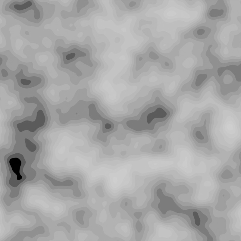
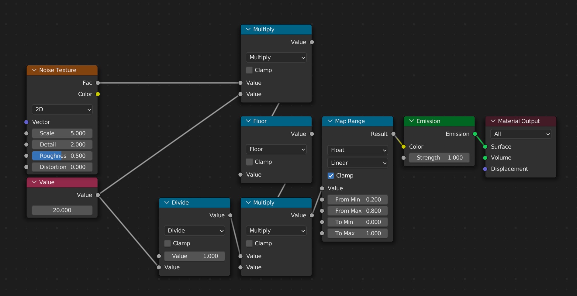
Not bad! Already, we have some basic terraced terrain that looks pretty good. We can even control the amount of terrace levels with a single number (the Value node on the left). Now how can we turn this into contours?
Edge Detection
The technique I used was to to take the image, shift if very slightly, then subtract the shifted image from the original. The pixels that become 0 are on the same level, which means whatever pixels are not 0 must be on a different level. These are the pieces of the image right on the edge!
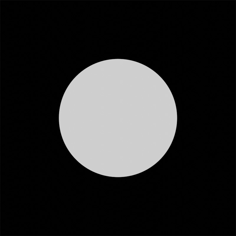
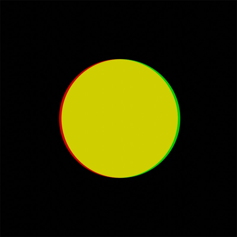
To illustrate, I’ll make a circle and show how edge detection could work there.
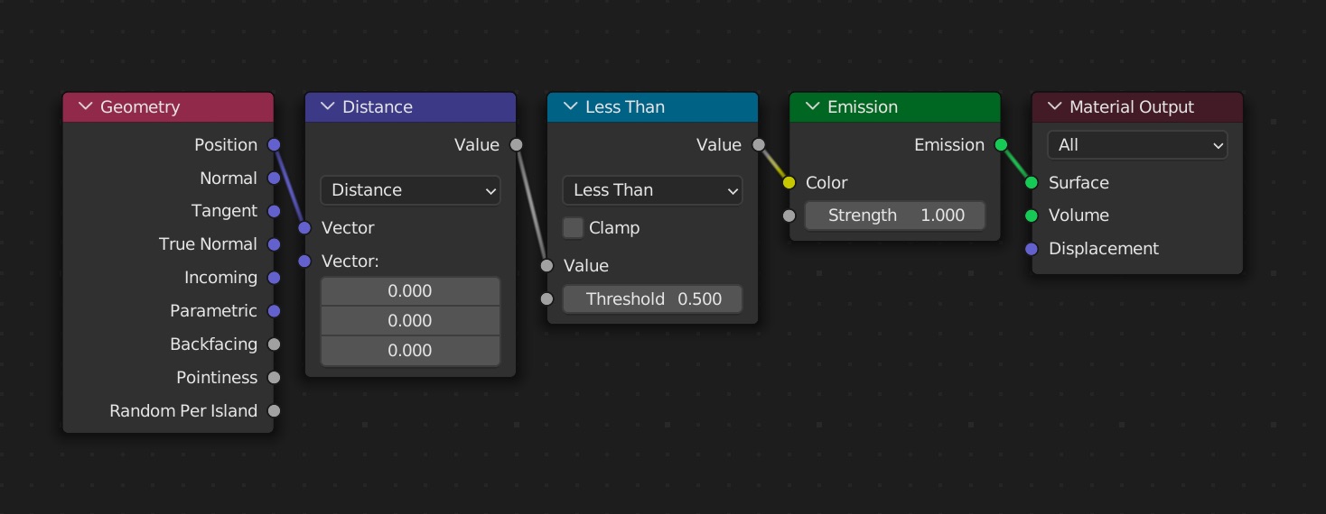
If we make a copy of that circle, shift if slightly to the left (positive X), then subtract it from the original, we end up with this:
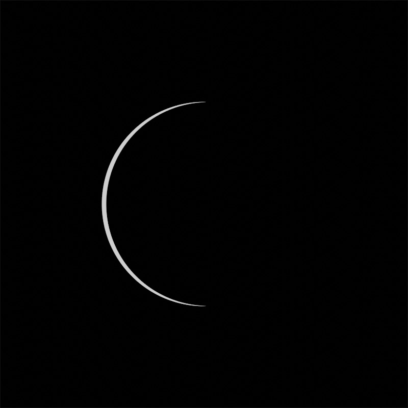
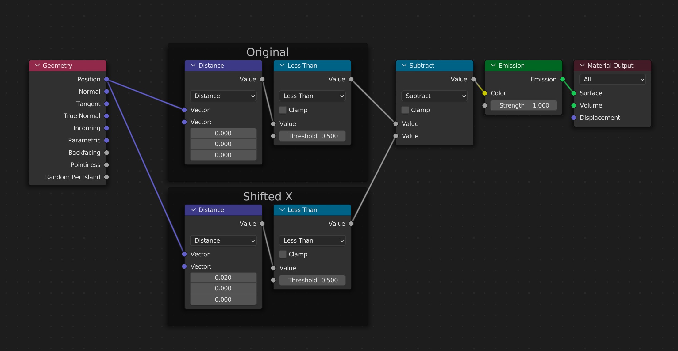
In as much as circles can have a left edge, we’ve isolated it. If we did this in four directions, we could approximate an outline. We can see this subtraction effect a little better if we superimpose the two circles together, making the original red and the shifted copy green:
Contoured Terrain
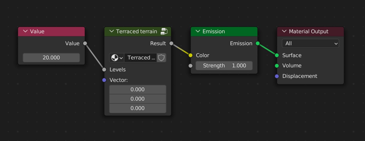
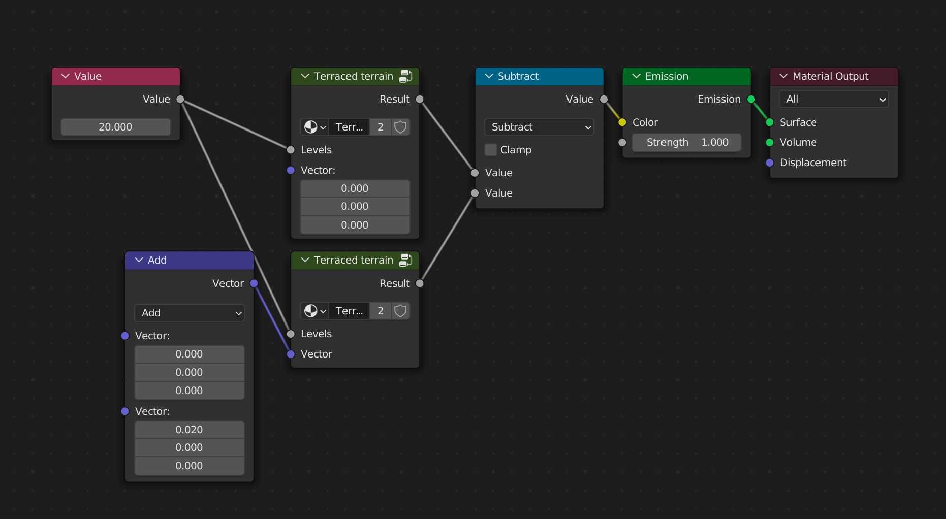
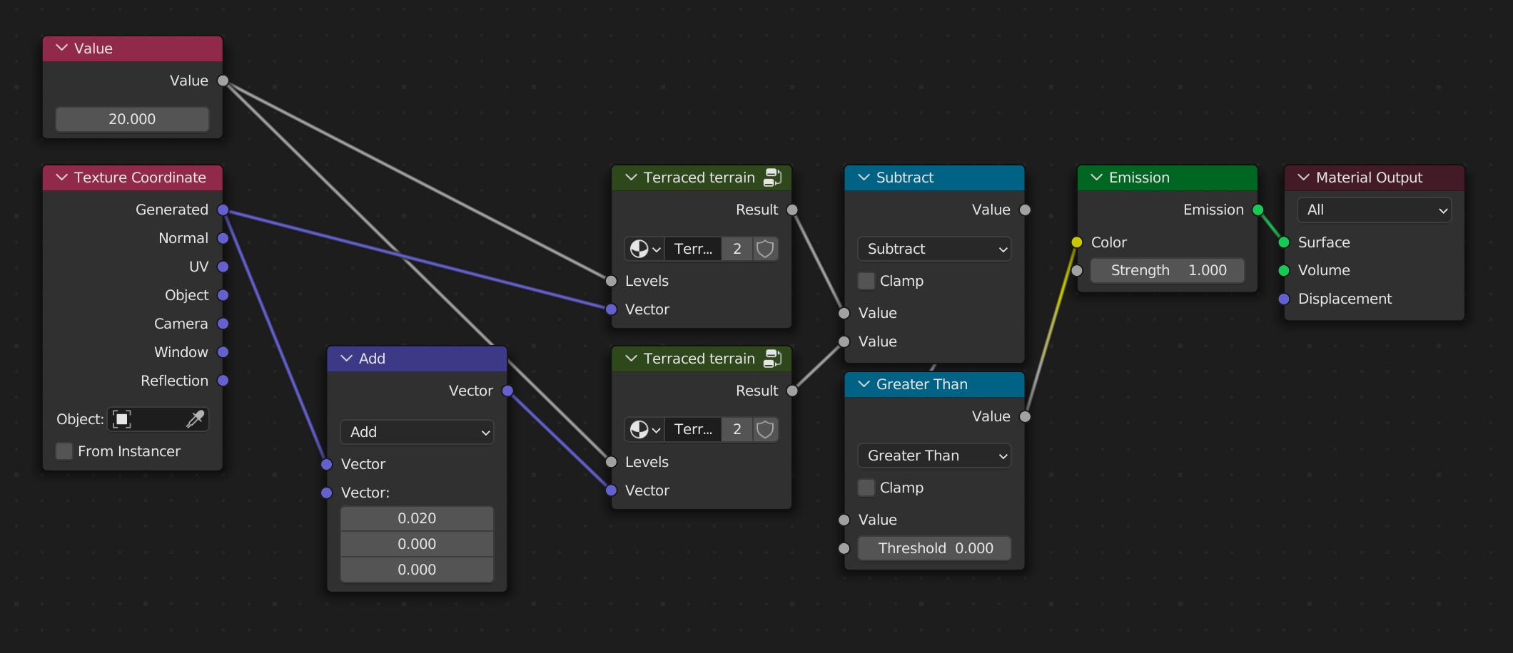
Now let’s apply this to our terrain. To make things a little easier to work with, since we’re going to use the terraced terrain multiple times, I’m going to put those nodes into a group with an input for the levels, and one for a vector so we can shift the noise around.
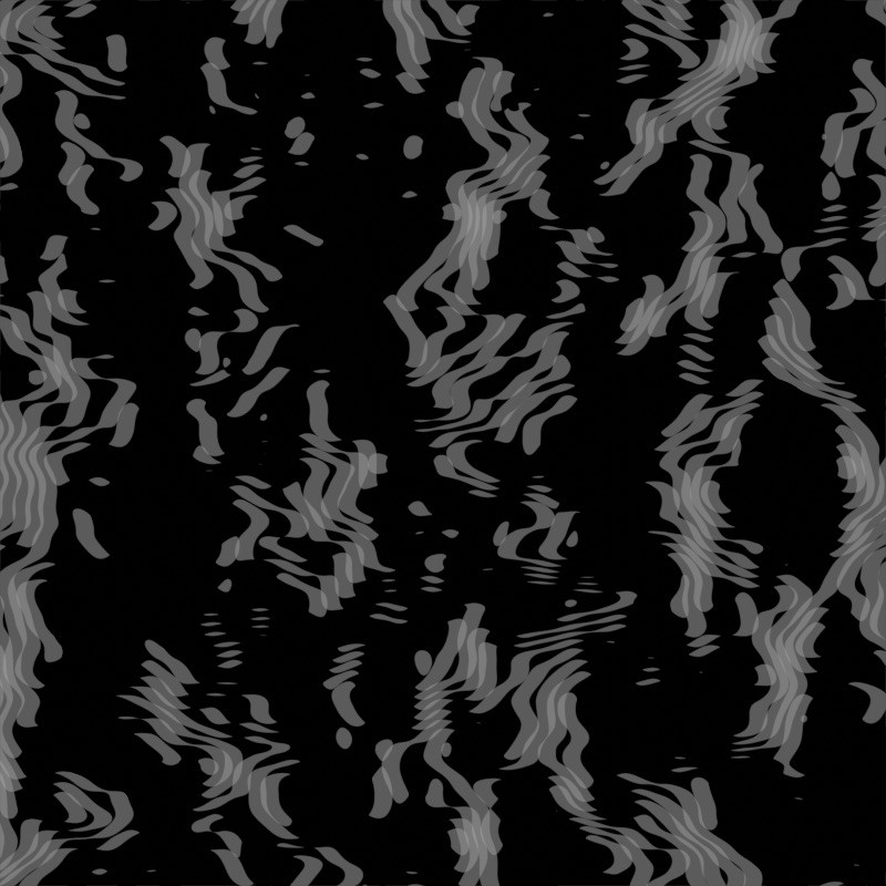
Now we make a copy, shift it, and subtract it from the original like we did with the circle.
Hmmm… It’s interesting, but not what we wanted. Turns out there are two problems.
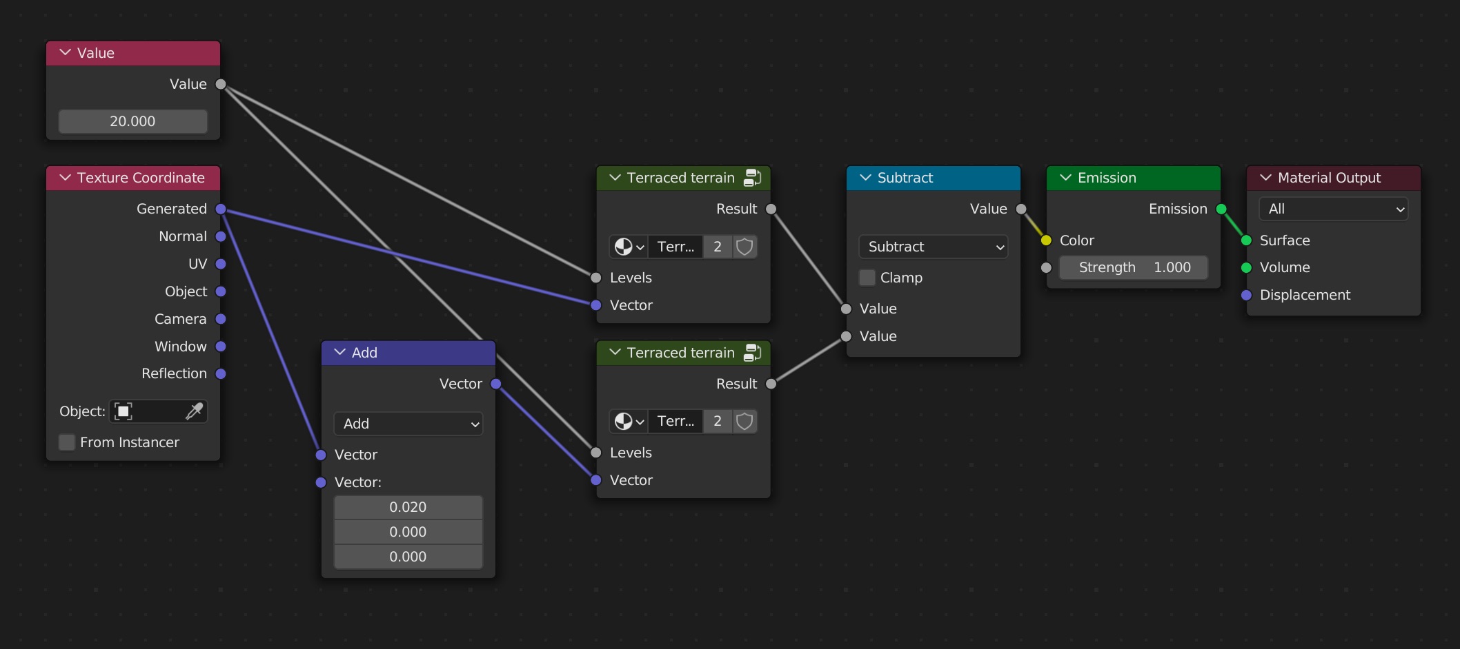
First, we need to use the same vector space for both terrains if we’re going to shift one. Currently the second terrain just used a static vector of (0, 0, 0) and subtracted 0.2 from x. This effectively makes the whole noise all the same color because the input vector never changes. To fix this, we can use the Texture Coordinate node and its Generated socket to get what we originally had.
That’s most of it. The second thing is that subtraction worked great for a simple circle since it was only black or white; 0 or 1. However, we are dealing with lots of in-between values for the different levels of our terrain. Each level will still subtract from itself to get to 0, but if the levels are close enough they can overlap which looks weird and slightly transparent.
The solution is to add in a Math node set to Greater Than 0. That means any value that isn’t 0 will show up as white. This also combines overlapping levels to be one solid color.
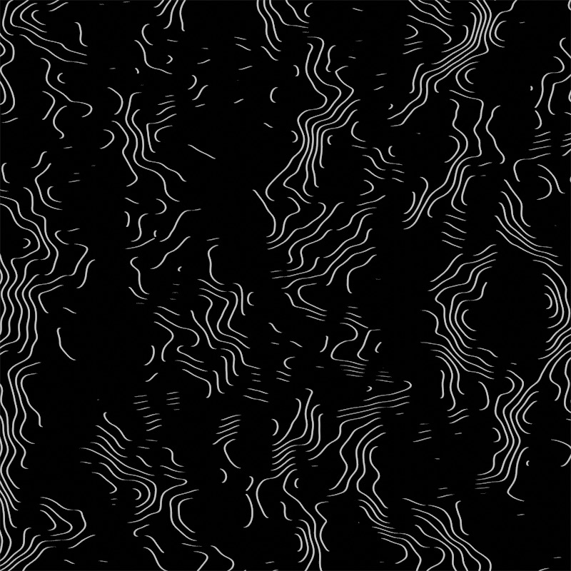
This isn’t exactly a problem, but the lines look a little thick to me. I’ll lower the amount we’re shifting by 10x from 0.02 to 0.002 to make the lines sharper.
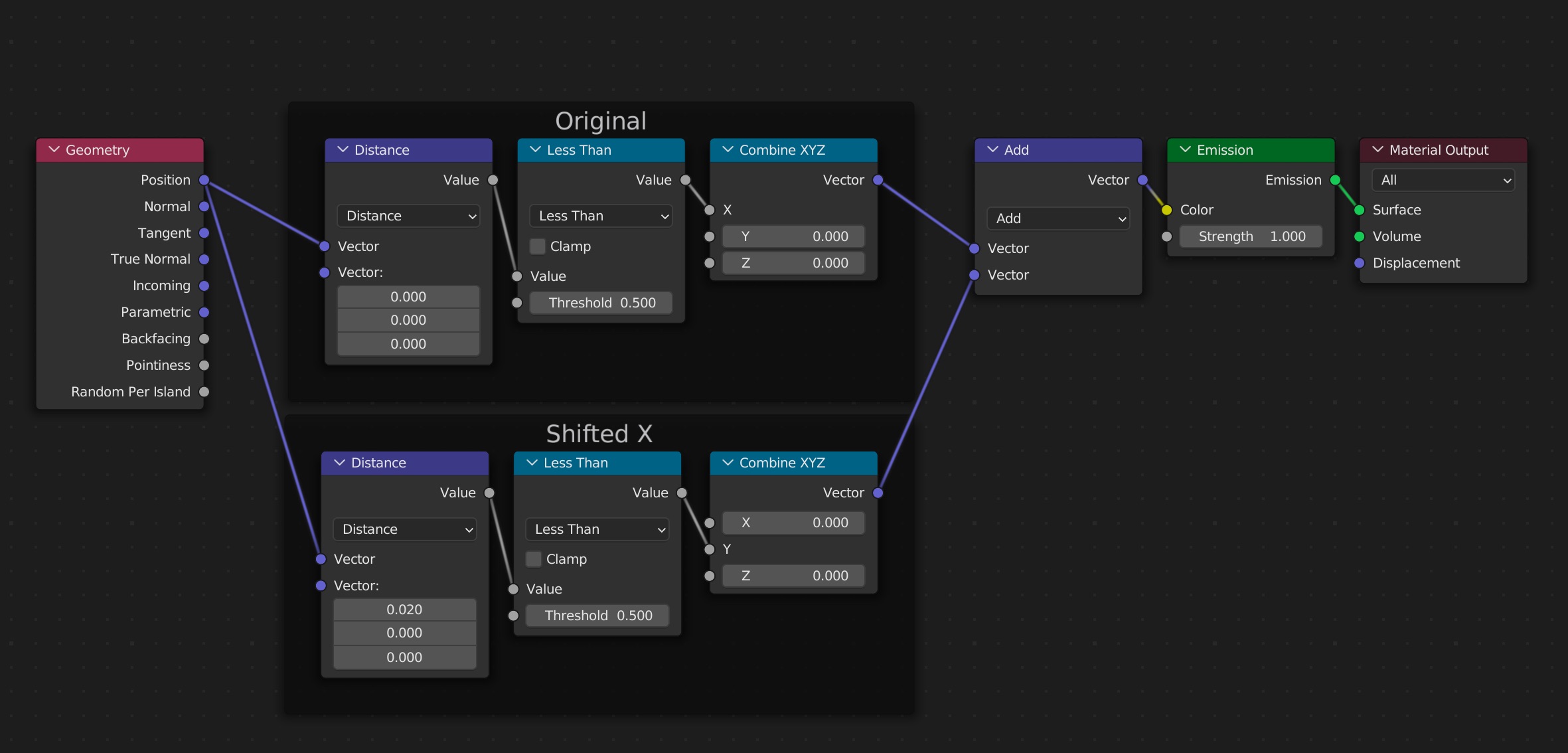
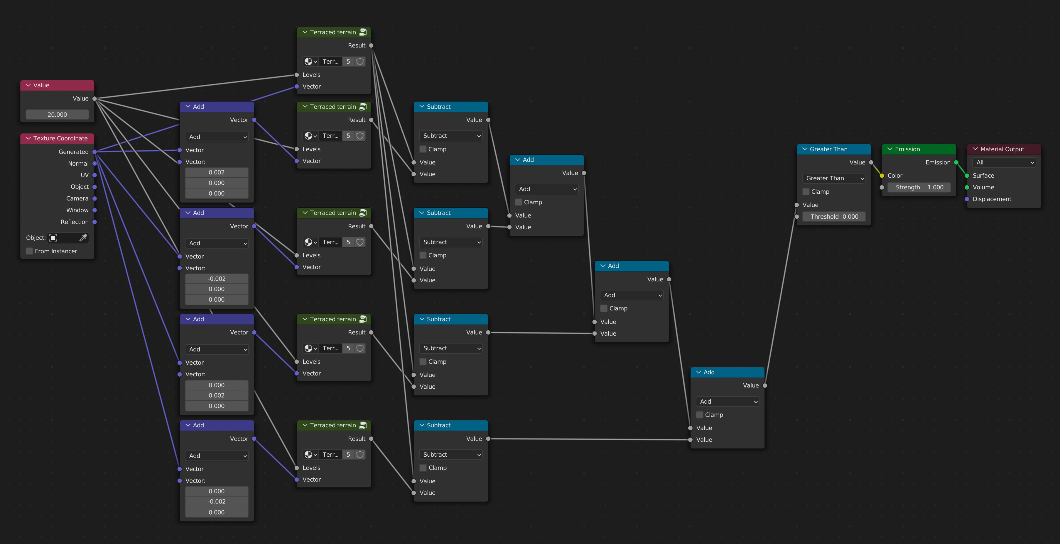
Now the only remaining steps are to create and subtract the three other sides, and add them all together. This can start to look a little overwhelming. Take comfort in that it’s only because there are lots of nodes and connections between them, not because this is complex math.
The process is:
- Duplicate the
Terraced terraingroup and vector Add node - Hook up the value to the
Levelsinput - Hook up the
Generatedcoordinates to the Add node - Use the Add node to shift the terrain slightly one direction
- Subtract the shifted terrain from the original terrain
- Add the previous terrain to the new one
- Put everything through the Greater Than node at the end
Like I said, complex looking, but not complex math. Here’s a picture of the final result:
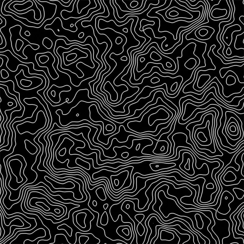
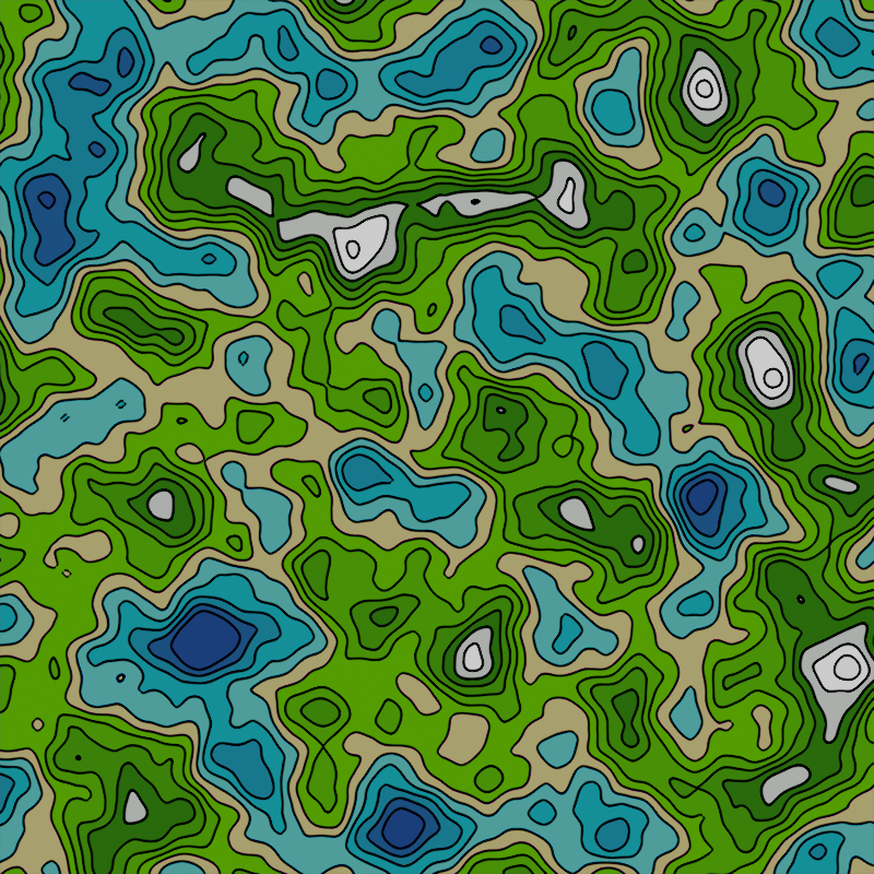
That looks pretty good to me! Now that you have this, you could then take these lines and superimpose them on the original terrain, add colors, shift the properties of the terrain to make it look different, or even add some underlying noise to the terrain itself to make different shapes. I myself made colorful terrain which you can see at the top. Enjoy!