


Overview
This beginner-friendly article will show you how to build a user counter display for your Auth0 tenant with Arduino. The user count will be displayed on a retro-style 7-segment display which you can place in a custom case, mount within a shadow box, or show it as is. You'll learn the basics of wiring circuits, programming a microcontroller, and how to authenticate IoT devices using Auth0.
The article is split into two parts. The first part will show you how to prototype the circuit and program the board to display digits on the 7-segment displays. The second part will cover building and deploying a simple user count API, setting up an Auth0 rule, setting up authentication, and soldering the final circuit.
What is Arduino?
Arduino is an open-source platform that includes hardware and software used to build electronics projects. The original goal of Arduino was to abstract away the complicated details of electronics so that anyone could build out their ideas. The platform is popular because it is easy to learn, the components are inexpensive, and there is a great community to help inspire and implement new microcontroller projects.
In this project, you will use the Arduino IDE to write a program (called a sketch) and upload it to a development board called the NodeMCU. The NodeMCU runs on a WiFi microchip called the ESP8266. This microchip makes it possible for the board to connect to WiFi and make HTTP requests. The NodeMCU is great for IoT projects because you can leverage the Arduino platform's conveniences while maintaining a small budget, as you can purchase these boards for a few bucks apiece.
Prerequisites
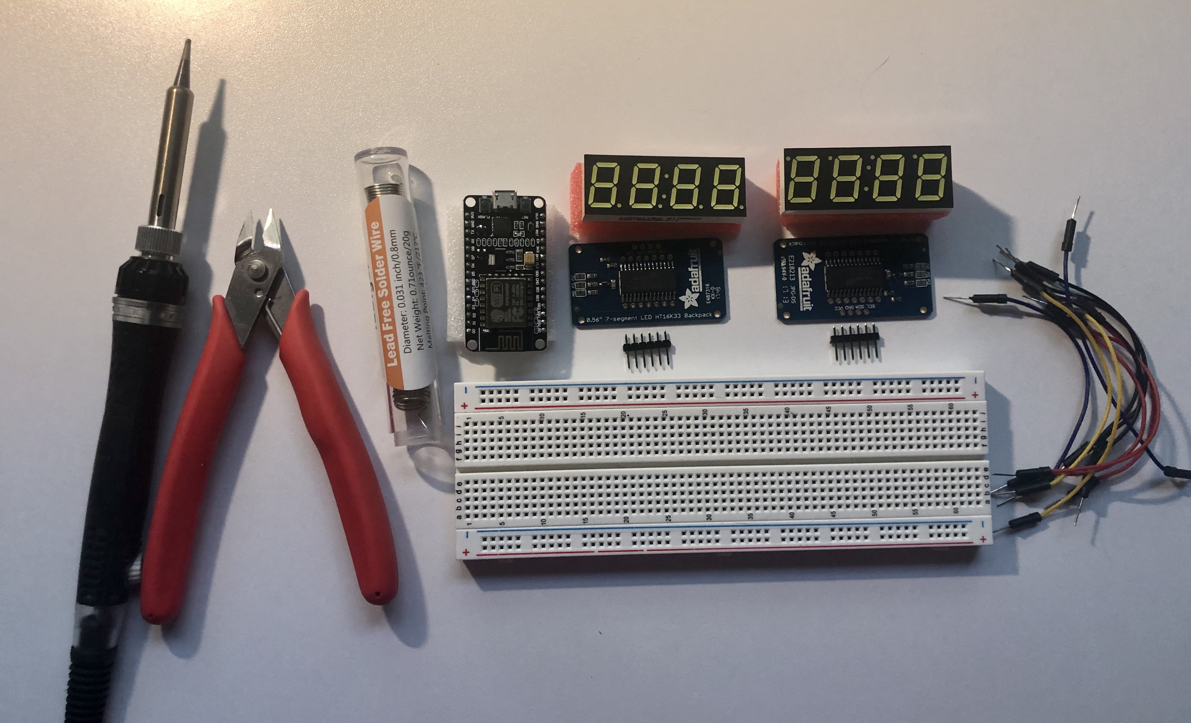
Here is a list of components, tools, and software you’ll need to build the user counter (links provided as examples of what you can use):
Components & Tools
- NodeMCU ESP8266 board
- Two Adafruit 0.56" 4-Digit 7-Segment Display w/I2C Backpack
- Micro USB wire with charge and sync
- Solderless breadboard
- Jumper wires
- Soldering iron and solder
- Narrow-blade wire cutters
If you want to make the circuit permanent (instructions in part two):
Software
Build the Prototype
Before soldering a circuit, it is helpful to create a prototype using a solderless breadboard. This allows you to test your program and circuit before permanently soldering the project together.
To build the prototype, you will need:
- 2 Adafruit 0.56” 7-segment displays with backpacks
- NodeMCU ESP8266 board
- Solderless breadboard
- Jumper wires - 3 red, 3 black, 2 yellow, and 2 blue
- Soldering iron
- Solder
- Narrow blade wire cutters
- Micro USB wire with sync
⚠️ Do not plug in the NodeMCU while wiring up the prototype. It’s easy to misplace a pin and create a short circuit. Plus, you don’t want to get shocked! Only plug in the board once you are done moving pins and wires.
Install the ESP8266 Core for the Arduino IDE
Before you begin prototyping, you’ll want to make sure that the Arduino IDE can communicate with the NodeMCU board. The NodeMCU was not built specifically for Arduino. In fact, the firmware is not even based on the same programming language (Arduino uses C/C++, and the NodeMCU firmware is based in Lua). Luckily, the Arduino IDE supports adding multiple board managers to compile programs into the microcontroller's language. It does this through a collection of components and libraries called a core. To communicate with the NodeMCU board, you will need to import the ESP8266 Core for the Arduino IDE as a board manager. This board manager will allow you to program the NodeMCU using Arduino functions, add relevant examples to help you get started, and install libraries that will make it simple to connect to WiFi and make HTTP requests.
Open the Arduino IDE and go to Preferences (on macOS, select Arduino > Preferences; on Windows and Linux, select File > Preferences).
Paste the following URL into the “Additional Boards Manager URLs”:
http://arduino.esp8266.com/stable/package_esp8266com_index.json
Click OK.
Go to Tools > Board > ESP8266 Boards and select NodeMCU 1.0.
Go to File > Examples > ESP8266 and select Blink
A code editor will open with the "Blink" example sketch.
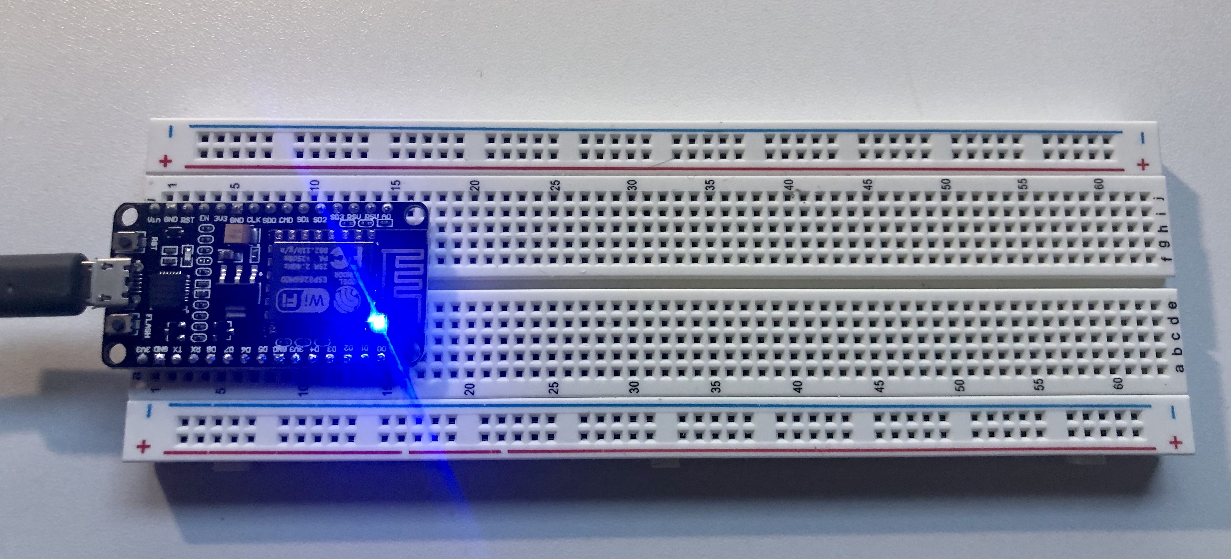
Place the NodeMCU board into your breadboard and connect the micro USB wire to your computer and the board.
Click the right-facing arrow on the top left to upload the sketch to the board.
As you might have guessed, when the sketch finishes uploading, a blue light begins to blink.
This means that the NodeMCU board is ready! Be sure to unplug the micro USB wire before moving on.
Assemble 7-segment displays
The next step is assembling the 7-segment displays. The Adafruit 7-segment displays should come with three components: the 7-segment display, a backpack, and a header. Before moving on, you will need to solder these pieces together.
To begin, you'll need to get the soldering iron ready. Make sure that the soldering tip is clean. Plugin your soldering iron and heat it to 300-350 degrees Celsius. For lead-free solder, you will use a higher temperature. Be sure to keep the iron in a safe spot.
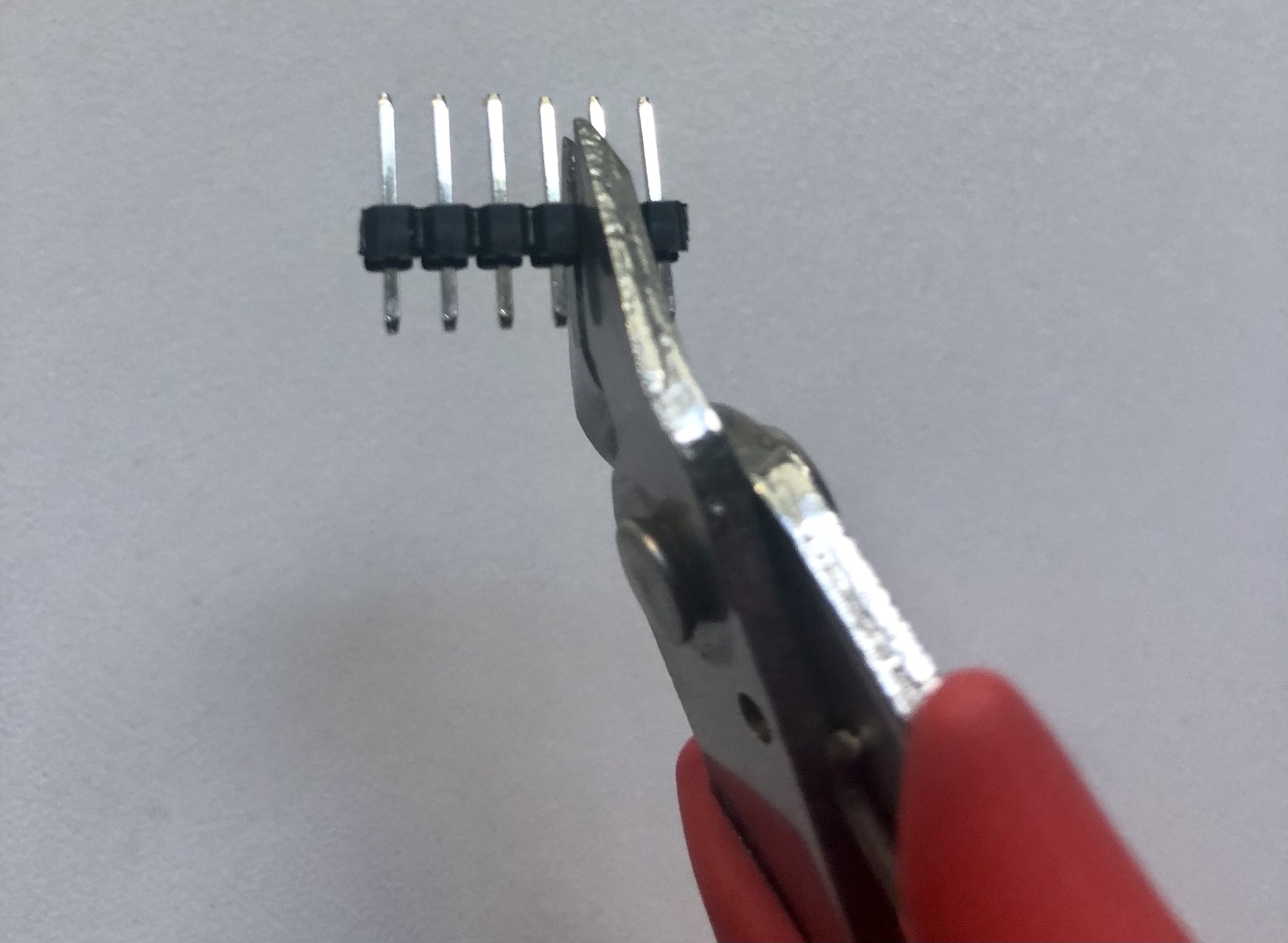
Next, you will prepare the 7-segment display components. My header piece had six pins, but the backpack only requires four pins, so I cut off two from each header. You may have to do the same if your backpack header has more than four pins.
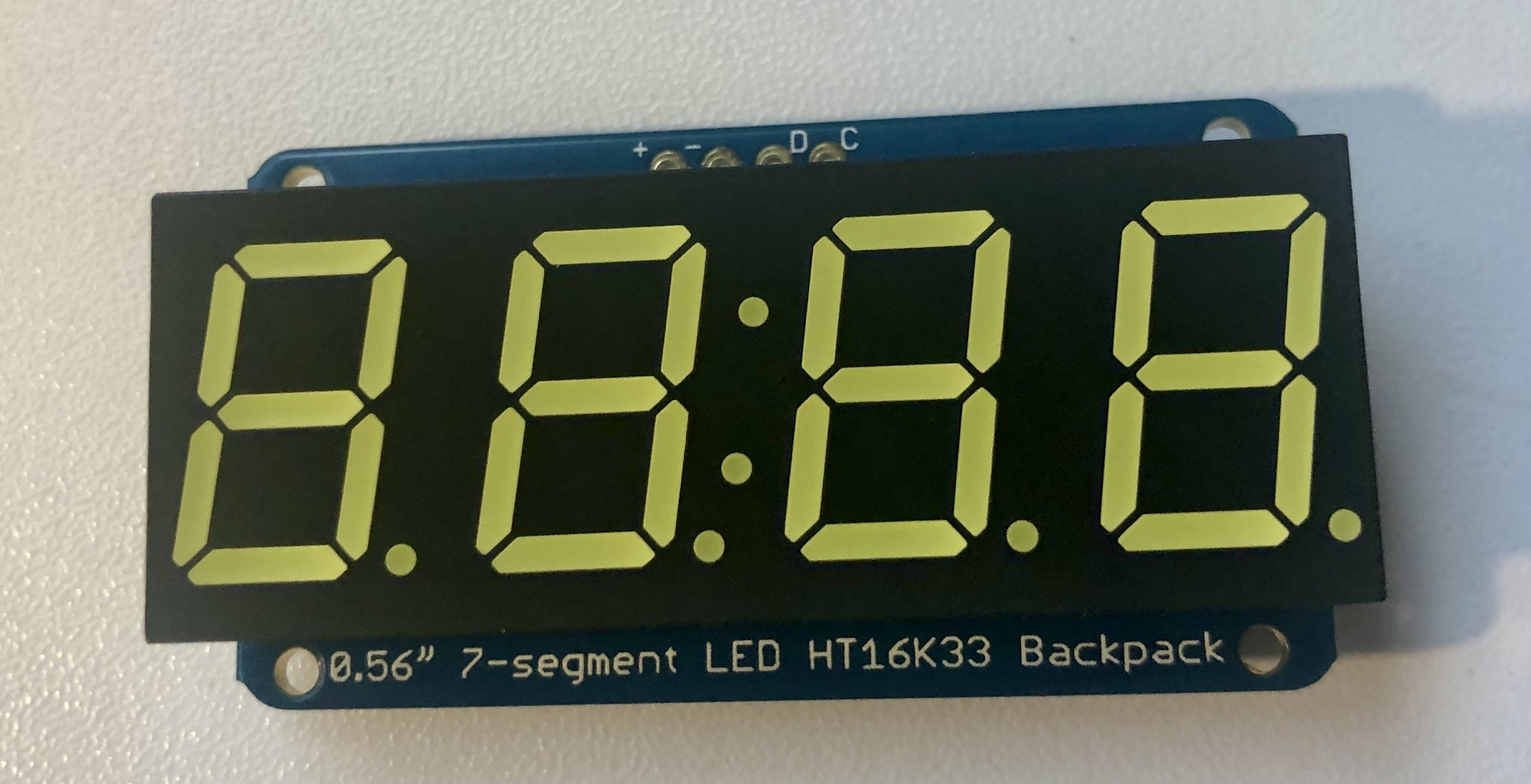
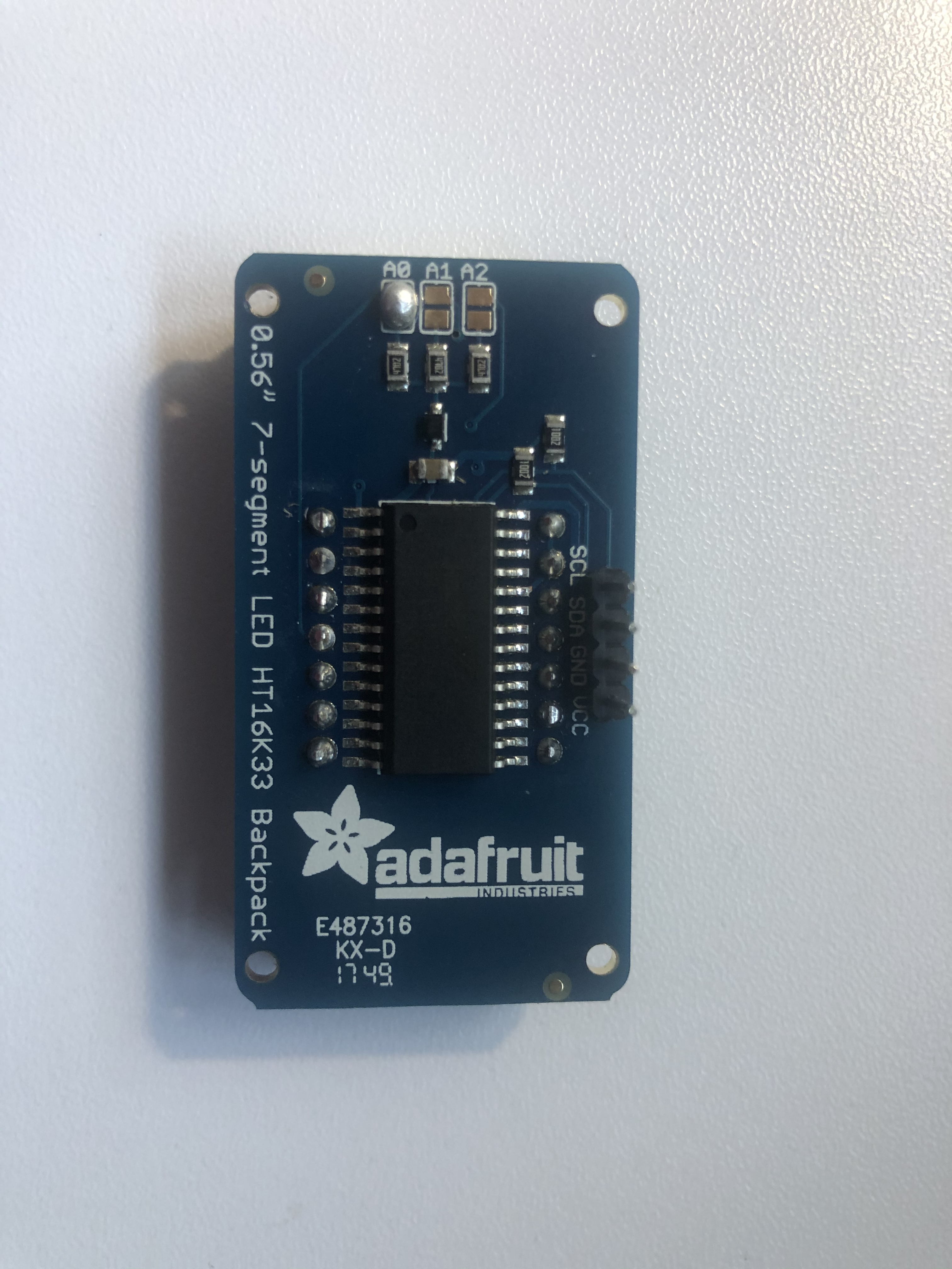
Place the backpack onto the display. You can tell which side is the bottom of the display by the four dots. Be sure that the dots on the display are on the same side as the “0.56” 7-segment LED HT16K33 Backpack” text. This is very important because if you solder the backpack upside down, it will not work.
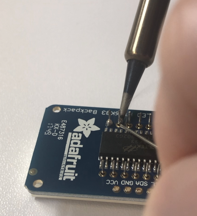
Flip the display and backpack over and solder all 14 pins.
💡 Soldering tip: Place the soldering iron tip next to the pin's base and touch the solder to the pin. Try not to touch the solder directly to the soldering iron. The goal is for the melted solder to flow around the pin's base to create a nice connection. Keep the soldering iron at the pin's base as you remove the solder and then remove the soldering iron. The order in which you remove the iron and solder is important because if you remove the soldering iron first, the solder can cool, and the strand of solder will be stuck to the pin.
After the pins have been soldered to the backpack, use wire cutters to trim the pins. Cut them just above the solder.
Now that the backpack is attached, you will need to solder the header. Place the long side of the header into your solderless breadboard.
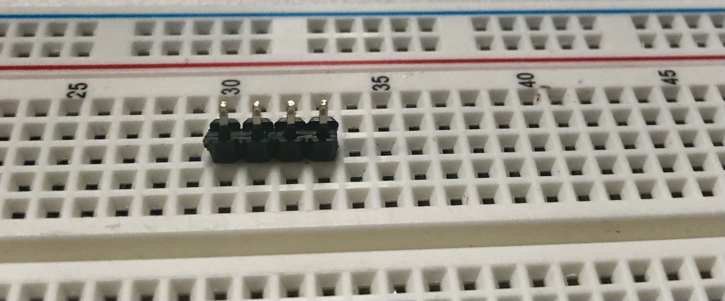
Place the 7-segment display over the header and solder each of the four pins.
Repeat this process for the second display.
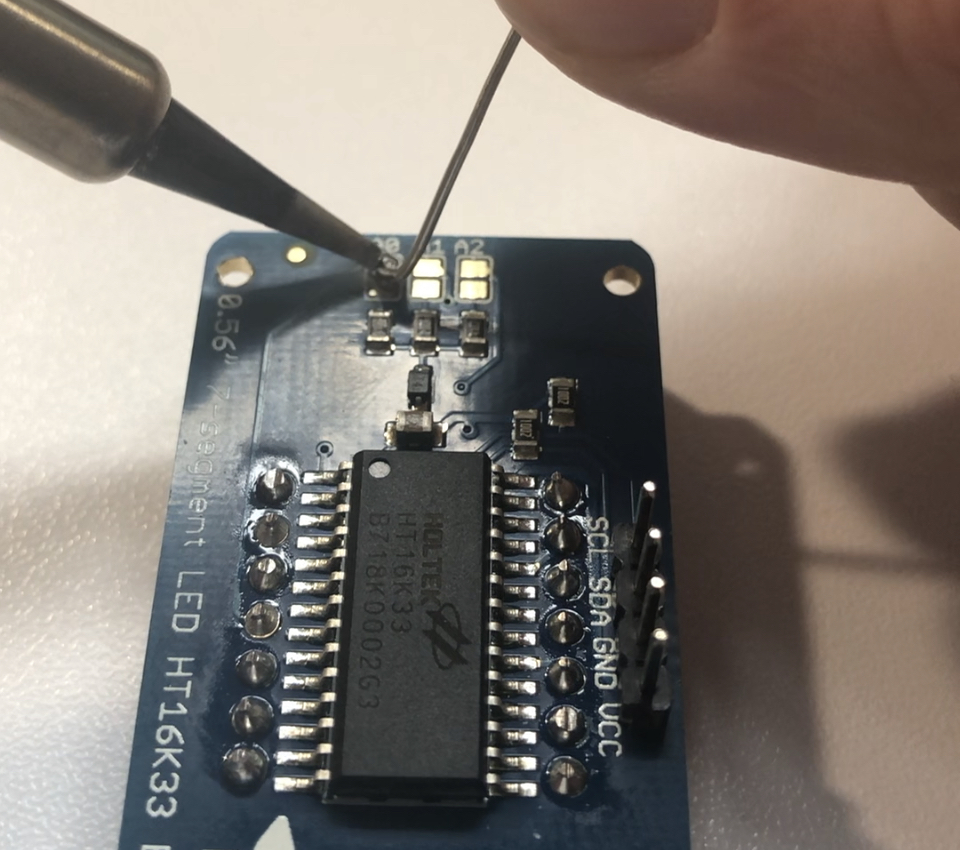
When you program the board, you will need to send different sets of numbers to each 7-segment display. To distinguish the two displays, you'll need to change the I2C address of one of them. The Adafruit backpacks allow you to do this with a feature called solder jumpers. The solder jumpers are located on the back of the backpacks and are labeled as A0, A1, and A2. If you short any of the solder jumpers by adding solder to them, it changes the 7-segment display's I2C address.
To show how this works in an Arduino sketch, the displays are initialized like this:
void setup() {
  Serial.begin(115200);
  highDigitDisplay.begin(0x71); // ← This is the display that has a shorted A0 solder jumper
  lowDigitDisplay.begin(0x70);
}
The I2C address of the display that has no solder bridge is 0x70, and the address of the display with the shorted A0 solder jumper is 0x71.
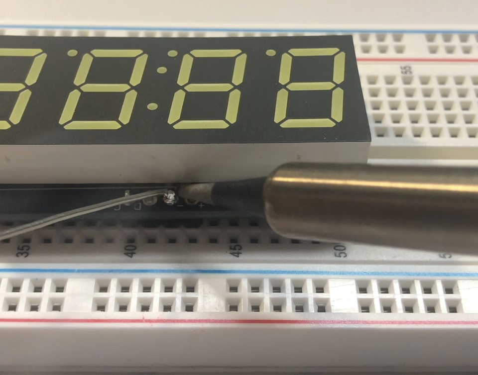
Melt solder over A0 on the back of one of the displays so that it now has a new address.
Wire up the circuit
Now that the components are prepped, you can begin wiring up a prototype.
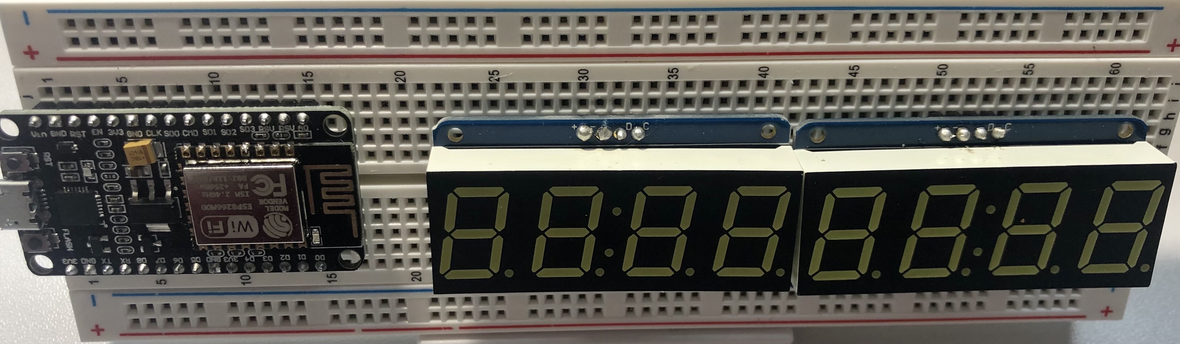
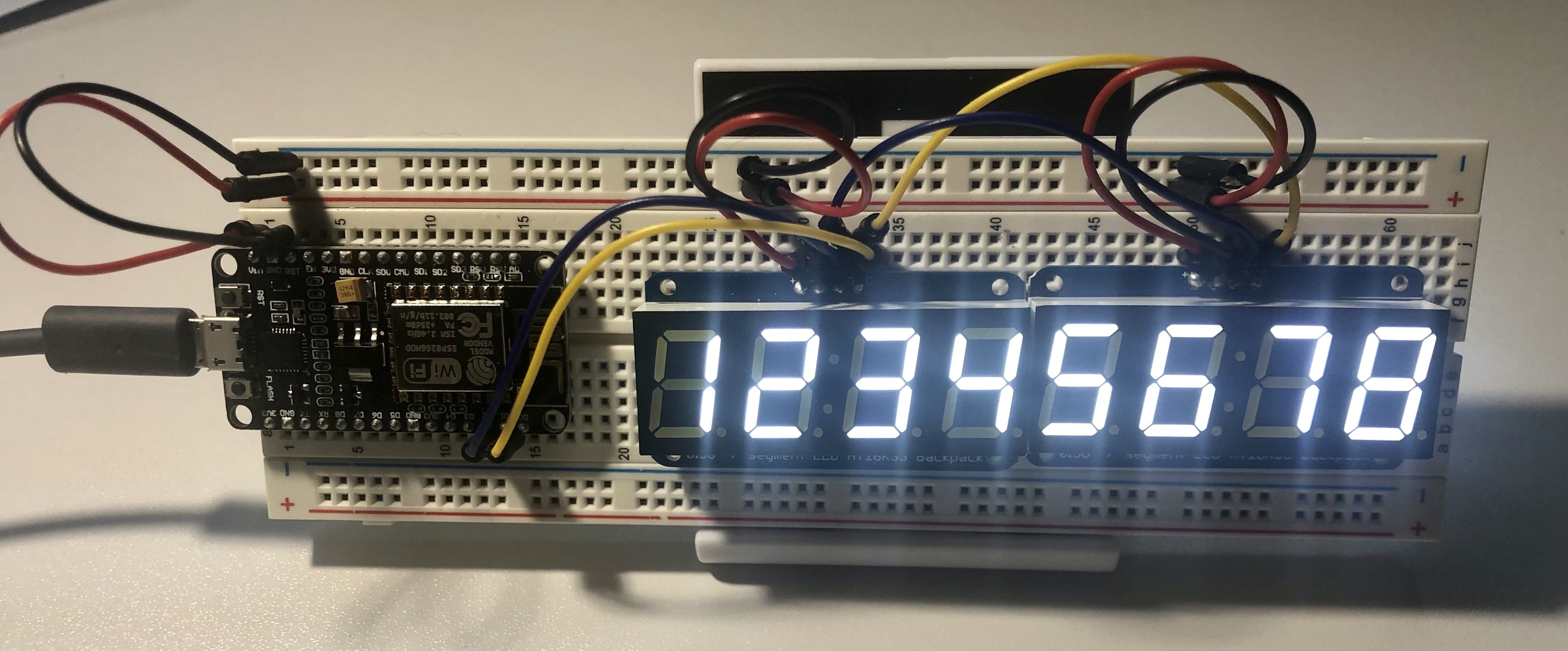
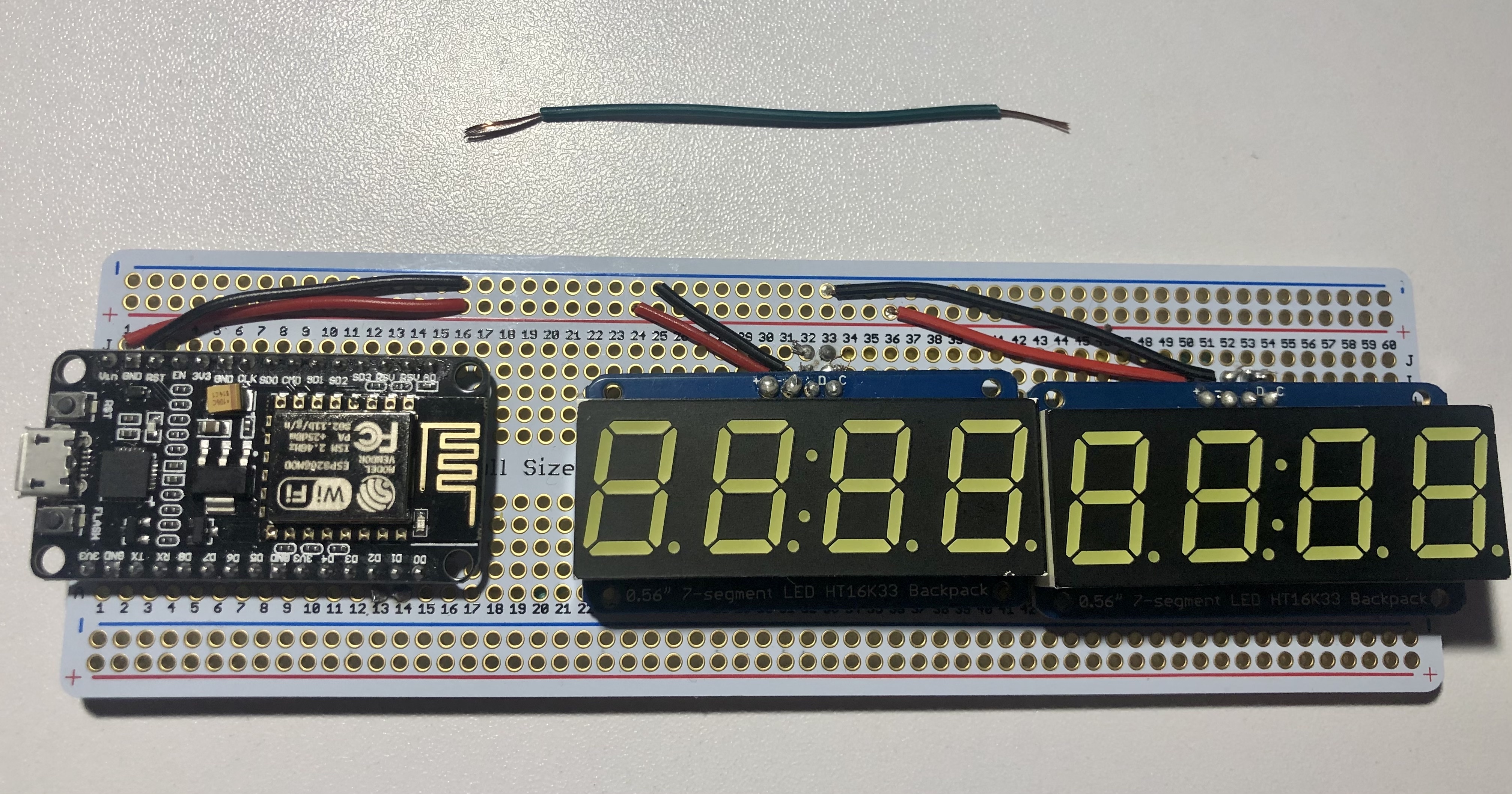
First, insert the NodeMCU board and two 7-segment displays into the breadboard. Make sure that the display that has solder over the A0 bridge is on the left. The black plastic part of the headers should touch the breadboard.
To make sure there is room for the jumper wires, the NodeMCU should have one row above it and one row below it. The 7-segment displays should have two rows above them.
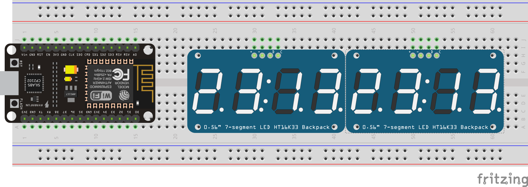
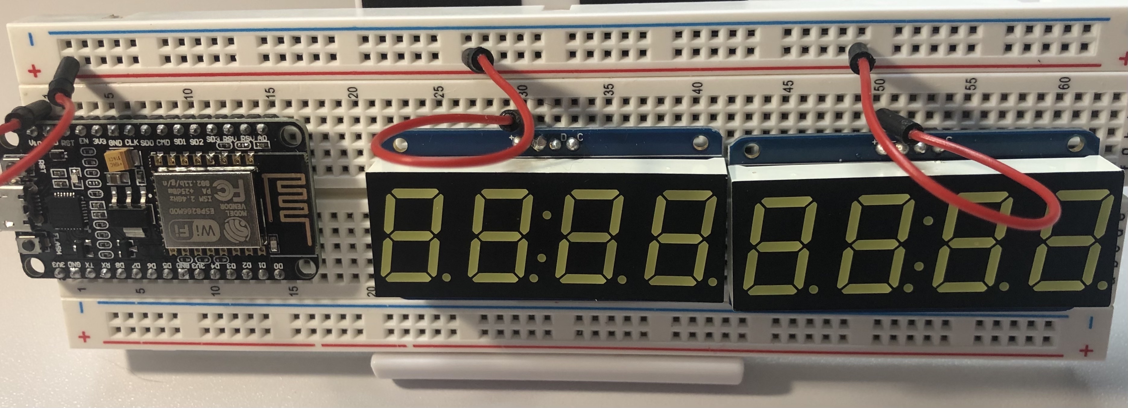
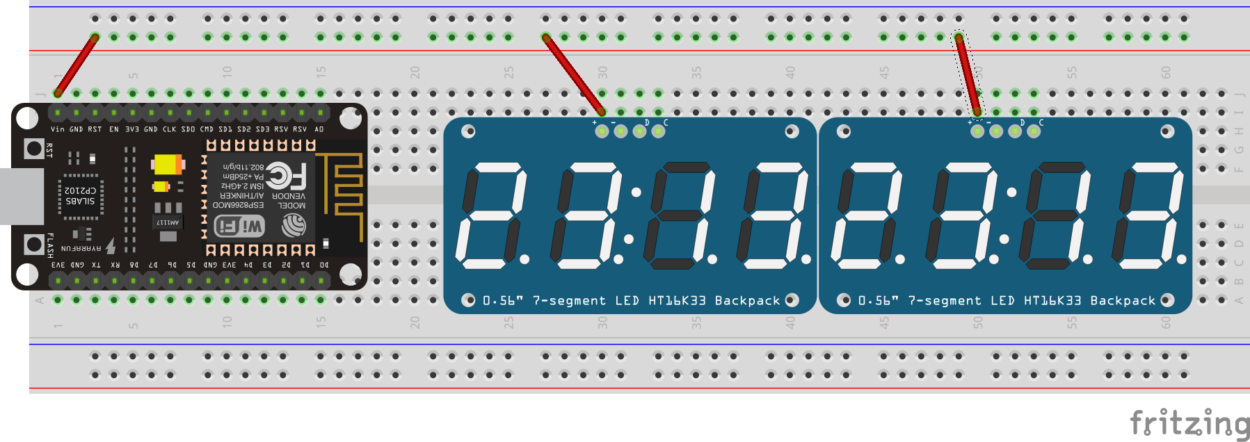
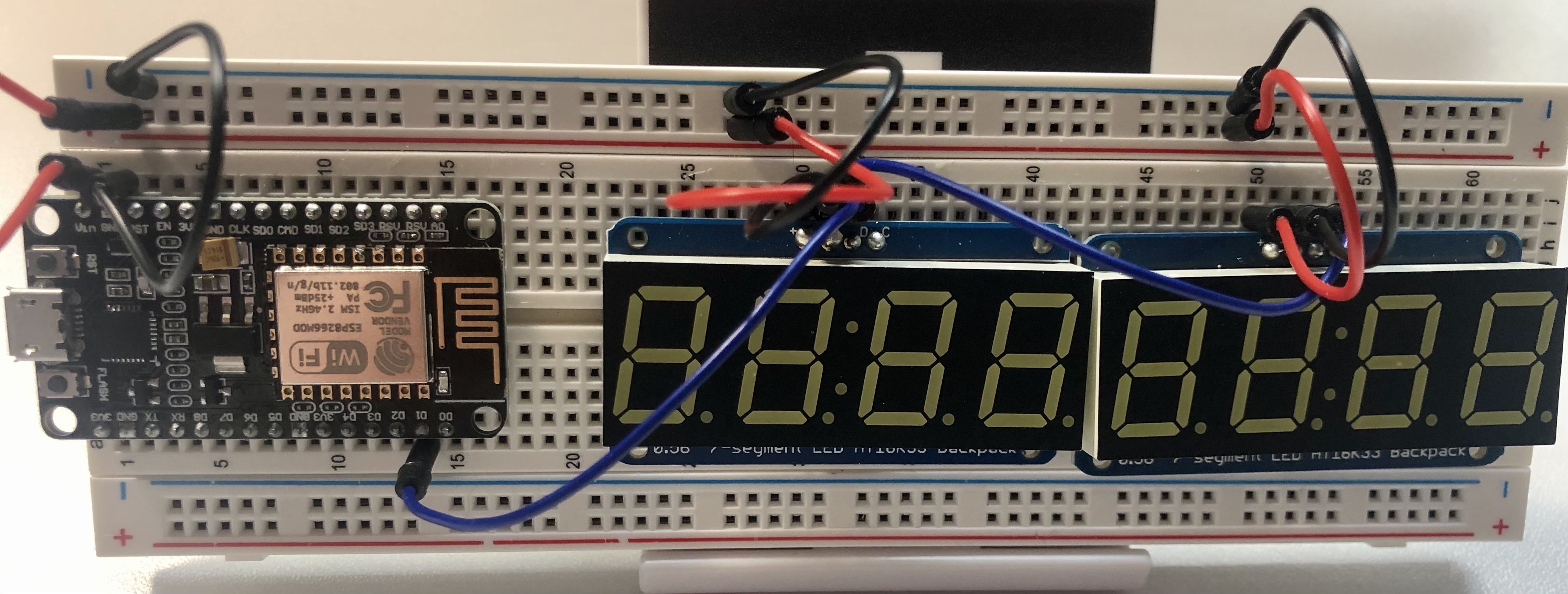
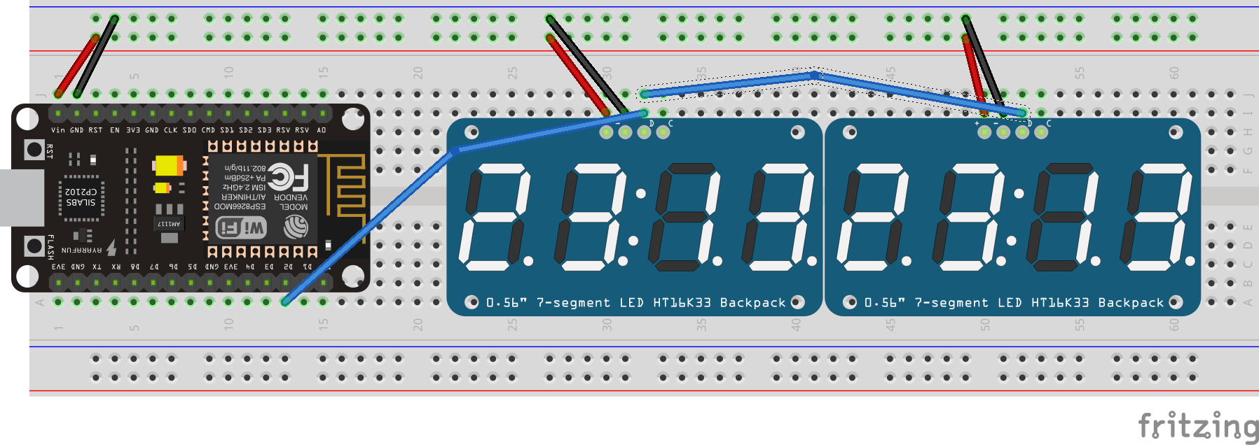
In the picture below, the NodeMCU Vin pin is in the i-1 hole, the left 7-segment display begins in h-30, and the right 7-segment display begins in h-50.
Next, you’ll set up the power for the prototype.
There are two connections required to supply power to the displays. First, you’ll need to route 5 volts to the displays. The NodeMCU can supply this through its external power pin, which is called Vin. Typically, a red wire is used for voltage, so use red jumper wires for this step.
On either side of the breadboard, there are strips called the power connectors. The blue row is used for ground power, and the red row is used for voltage.
As mentioned earlier, the NodeMCU’s Vin pin supplies the voltage you need. Insert one end of a red jumper wire next to the Vin pin (j-1). Place the other end of the wire into one of the holes beside the breadboard's red line.
Because the power connector rows run all the way across the breadboard, you can supply power at one end and source the power anywhere else on the board.
Take another red wire and place one end above the positive pin on the left 7-segment display (+). This is i-30 on my board. Connect the other end anywhere along the positive power connector row. Do the same for the right 7-segment display (i-50).
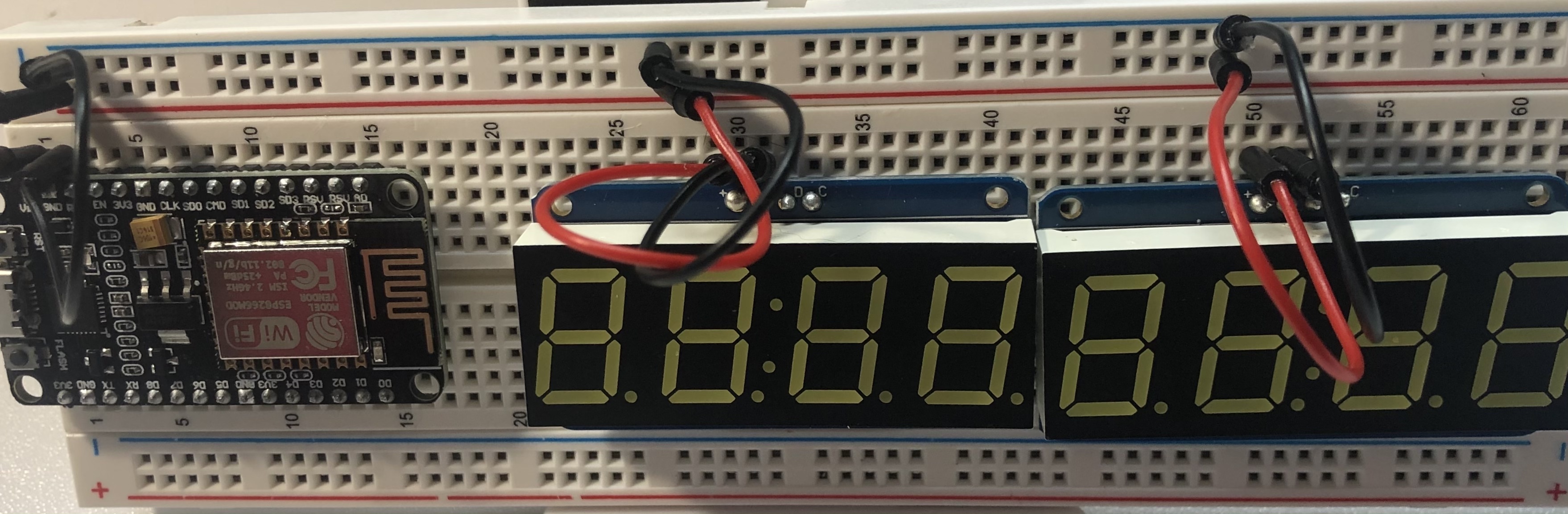
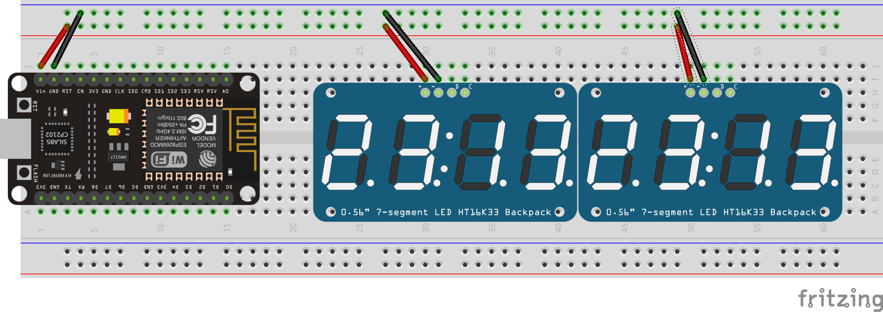
Next, grab three black jumper wires to wire up the ground power. One end of the wire should be placed next to the GND pin of the NodeMCU board. The other end should go anywhere along the blue line of the power connector of the breadboard.
Just like for the red 5V wires, insert the black wires beside each of the displays. The ground power should be connected to the negative pin of the displays (-). On my board, the black wires are connected to i-29 and i-49.
Now that you have supplied power, you’ll need to set up the communication between the NodeMCU and the 7-segment displays.
Normally, you would need 13 pins to control a 7-segment display (5 characters with 8 segments each), but you only need two pins to send messages to the displays because you are using the Adafruit backpack. The backpack allows for this by using the Inter-Integrated Circuit (I2C) protocol, a common communications method in microcontroller-based systems. I2C only requires two pins for communication, one for the Serial Data Line (SDL or I2C Data) and one for the Serial Clock Line (SCL or I2C Clock).
First, we’ll connect the SDL to the displays using blue jumper wires. Connect one end to the NodeMCU’s D2 pin (a-13) and connect the other end next to the D on the left display (i-32). Use a second blue wire to connect the two displays. One end goes right above the other blue wire next to the display’s D pin (j-32), and the other end goes next to the right display’s D pin (i-52).
Finally, connect the SCL with yellow jumper wires. With a yellow wire, place one end next to the NodeMCU’s D1 pin (a-14), and place the other end next to the left display's C pin (i-33). Just like you did for the blue SDL wire, connect the two displays with the second yellow jumper wire (j-33 and i-53).
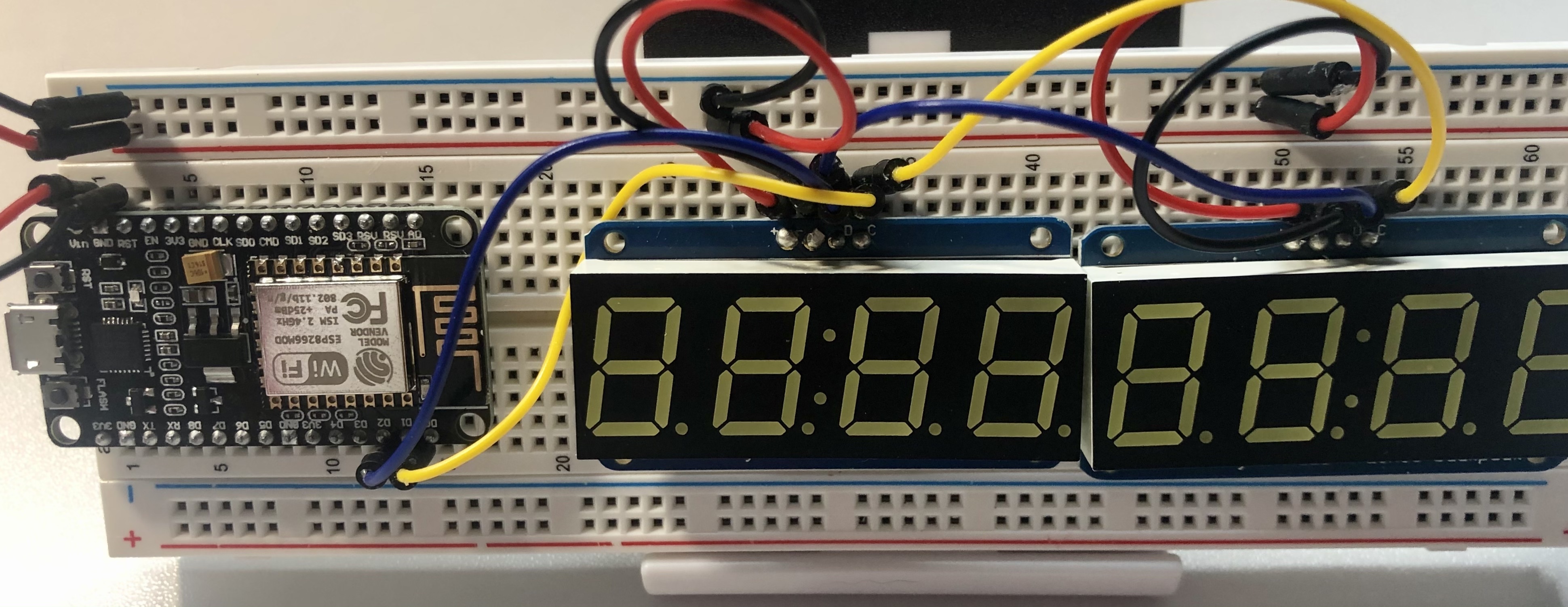
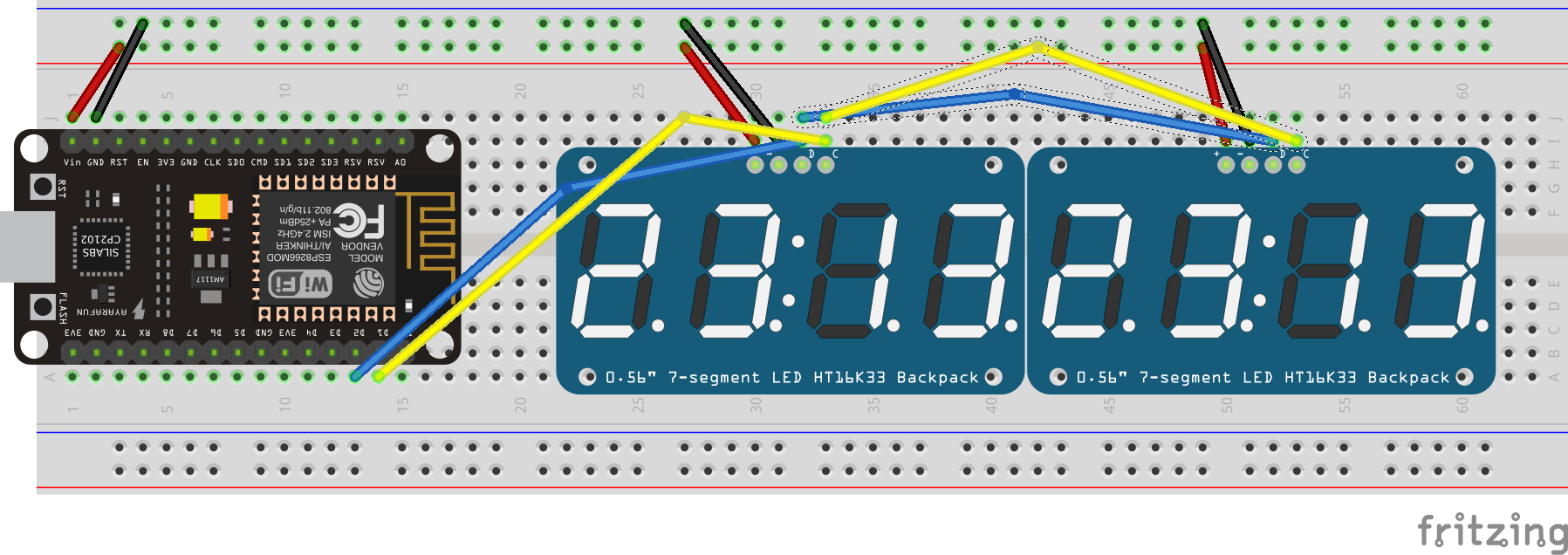
The circuit is complete!
Testing the prototype
You can now test your prototype.
Before you write your Arduino sketch, you will need to install a couple of libraries so that you can work with the 7-segment displays.
Go to Tools > Manage Libraries… and search for the “Adafruit LED Backpack Library” and “Adafruit GFX” and install each.
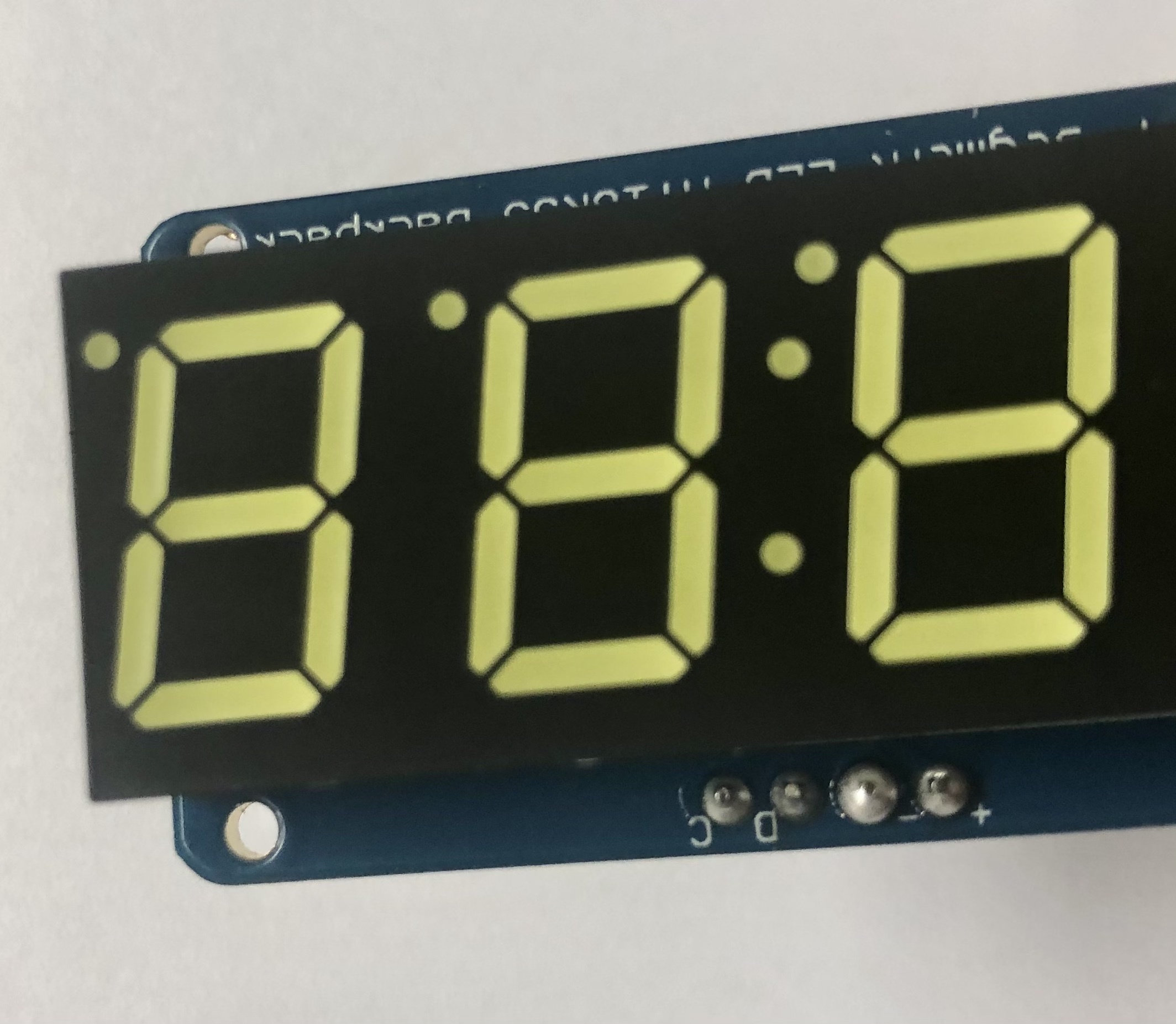
Copy the code snippet below to show “12345678” on the displays:
#include <Adafruit_GFX.h>
#include "Adafruit_LEDBackpack.h"

Adafruit_7segment highDigitDisplay = Adafruit_7segment(); // left-hand display - displays digits greater than 9,999
Adafruit_7segment lowDigitDisplay = Adafruit_7segment(); // right-hand display - displays digits less than 10,000

int userCount;

void setup() {
  Serial.begin(9600);
  highDigitDisplay.begin(0x71);
  lowDigitDisplay.begin(0x70);
}

void loop() {
  userCount = 12345678;
  Serial.println(userCount);
  uint16_t highDigits = userCount / 10000, // Value on left (high digits) display
           lowDigits = userCount % 10000; // Value on right (low digits) display

  highDigitDisplay.print(highDigits, DEC);
  lowDigitDisplay.print(lowDigits, DEC);

  // Place zeroes in front of the lowDigits value if userCount is 10,000 or greater, otherwise clear the highDigitDisplay
  if (highDigits) {
    if (lowDigits < 1000) {
      lowDigitDisplay.writeDigitNum(0, 0);
    }
    if (lowDigits < 100) {
      lowDigitDisplay.writeDigitNum(1, 0);
    }
    if (lowDigits < 10) {
      lowDigitDisplay.writeDigitNum(3, 0);
    }
  } else {
    highDigitDisplay.clear();
  }

  highDigitDisplay.writeDisplay();
  lowDigitDisplay.writeDisplay();
  delay(1000);
}
Here's a walkthrough of the code:
- The Adafruit libraries are imported so that you can use the
Adafruit_7segmentclass to interact with the 7-segment displays.
#include <Adafruit_GFX.h>
#include "Adafruit_LEDBackpack.h"- Next, you initialize variables. The two 7-segment displays are initiated as instances of the
Adafruit_7segmentclass. You also initialize an integer variable to store the user count.
Adafruit_7segment highDigitDisplay = Adafruit_7segment(); // left-hand display - displays digits greater than 9,999
Adafruit_7segment lowDigitDisplay = Adafruit_7segment(); // right-hand display - displays digits less than 10,000

int userCount;
When writing an Arduino sketch, you will always need to define two functions--setup and loop. The setup function is called first and only once. The loop function is called next and loops over and over again.
- In your setup function, you take care of two things: 1) begin the serial monitor (more on Arduino's serial monitor feature in part two!) and 2) initialize the 7-segment displays. Reminder: The highDigitDisplay is the display that has a solder over A0 on the back of the backpack. Its I2C address is 0x71.
void setup() {
  Serial.begin(9600);
  highDigitDisplay.begin(0x71);
  lowDigitDisplay.begin(0x70);
}- In the
loopfunction, you setuserCountto 12345678. You then use an operator called a modulo (%) to split up theuserCountbetween the high-digit display and the low-digit display.highDigitsisuserCountdivided by 10,000.lowDigitsis the remainder ofuserCountdivided by 10,000. These values are then printed onto the displays.
  userCount = 12345678;
  Serial.println(userCount);
  uint16_t highDigits = userCount / 10000, // Value on left (high digits) display
           lowDigits = userCount % 10000; // Value on right (low digits) display

  highDigitDisplay.print(highDigits, DEC);
lowDigitDisplay.print(lowDigits, DEC);- Next, the low-digit display is zero-padded. This is necessary for showing zeros in front of the
lowDigitsvalue. For example, if the user count is 10,005 and you do not add the zeros, then the displays will show "1 5". Also, if the user count is less than 10,000, the high-digit display is cleared.
  // Place zeroes in front of the lowDigits value if userCount is 10,000 or greater, otherwise clear the highDigitDisplay
  if (highDigits) {
    if (lowDigits < 1000) {
      lowDigitDisplay.writeDigitNum(0, 0);
    }
    if (lowDigits < 100) {
      lowDigitDisplay.writeDigitNum(1, 0);
    }
    if (lowDigits < 10) {
      lowDigitDisplay.writeDigitNum(3, 0);
    }
  } else {
    highDigitDisplay.clear();
}- Finally, the values are written to the displays using the
writeDigitNummethod. A one second delay is added to slow down the loop.
  highDigitDisplay.writeDisplay();
  lowDigitDisplay.writeDisplay();
  delay(1000);
Now that you have your sketch ready, it is time to upload it. Click the right-facing arrow in the top left of the editor to upload the program.
You can update the userCount to a different number and see it change when you upload the code again.
Solder the Final Board
Now that your prototype can display digits from your sketch, it is time to solder the final circuit.
You could keep your user counter on the solderless breadboard, of course. But if you want to hang up your project inside a shadow box (I highly recommend checking out Beck Stern's Instructables project!) or if you want to have a version of your counter that you can pass around, then this step is recommended.
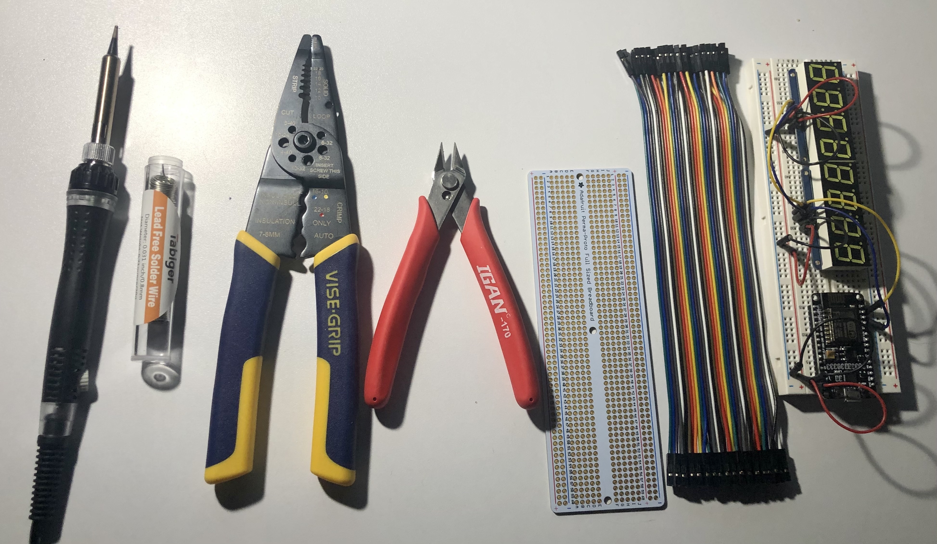
First, you will need to gather the required supplies. You can use additional tools to make the soldering job easier, such as flux or a soldering hand. However, I wanted to keep this project as budget-friendly as possible. Below are only the essential supplies you will need.
For this step, you will need: * Solder * Soldering iron * Wire strippers * Wire cutters * A full-sized perma-proto board * Wires * Your prototype
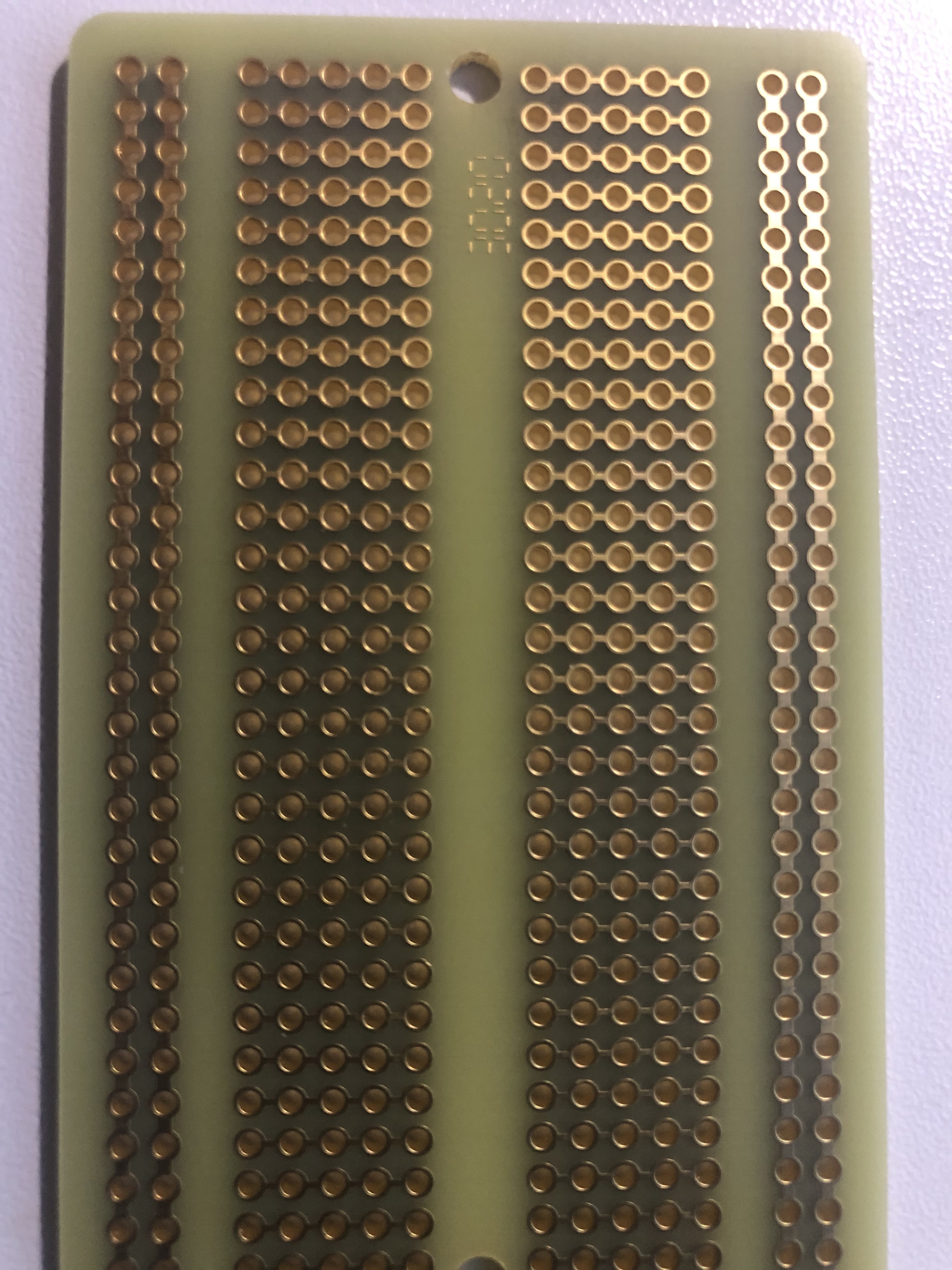
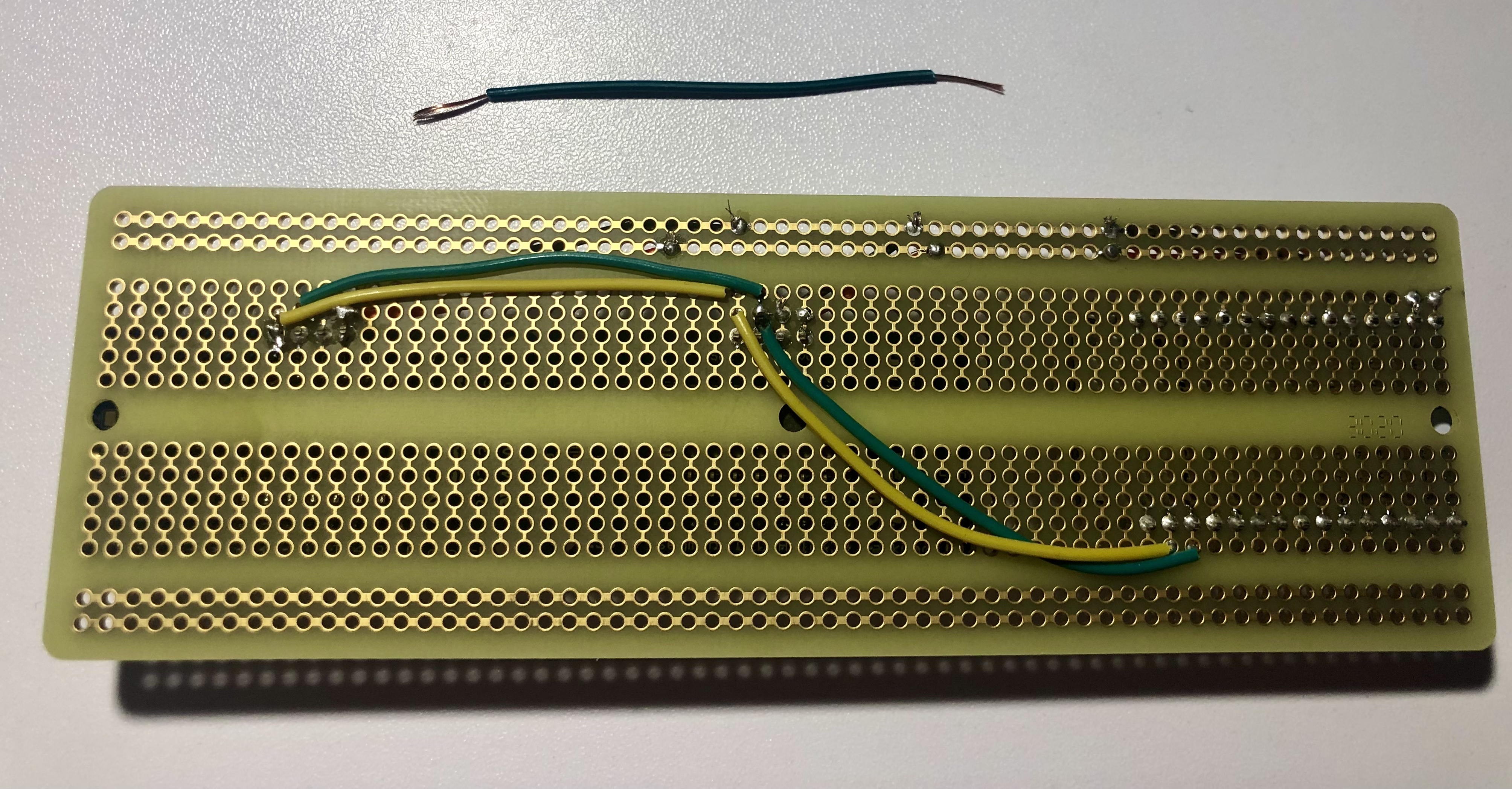
Before getting started, take a look at the Adafruit perma-proto board. If you look at the back, you can see how the circuit connects. Like in the solderless board, both sides of the board connect vertically, and the terminal between the power rails is connected horizontally. This means that you can connect the circuit the same way as the prototype.
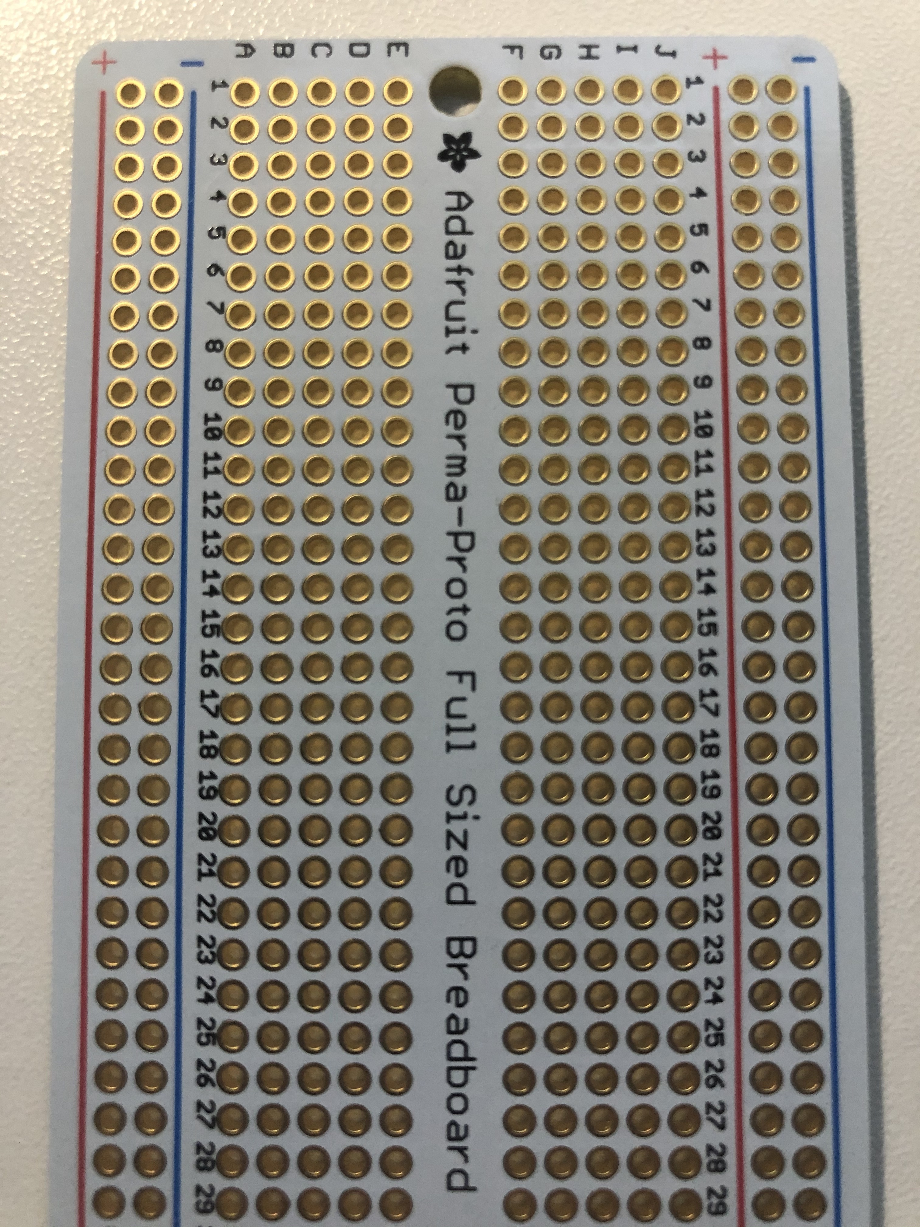
On the front side, a grid is labeled just like the solderless board. This means that you can refer to the diagrams above and use the same holes as the prototype for all of the wires.
Just like the prototype, first, place the NodeMCU on the perma-proto board. Flip the board over and solder all 30 pins. Use wire cutters to trim the pins.
One at a time, insert each 7-segment display and solder the headers onto the perma-proto board. Trim the header pins with the wire cutters.
Finally, using the prototype diagrams above, solder the wires for supplying power and setting up communication for the NodeMCU and the 7-segment displays. To do this, one wire at a time, cut it to be an appropriate length. Strip each end of the wire so that there is about a half-inch of exposed copper. Insert the copper ends into the perma-proto board, solder the back, and trim the excess wire.
Now that your circuit is complete, you are ready to start programming the board to call an API and display user count data. You will learn how to do this in part two.
Summary
In part one of this article, you learned about Arduino, wired up a prototype, wrote a sketch that displays a number on the 7-segment displays, and soldered the final circuit. In part two, you will finish the user counter by building and deploying an API, setting up a Rule to increment the user count, create a sketch that will call the API and parse the response, and finally, add authentication using Auth0 and OAuth 2.0's Device Authorization Grant.


