This post explains my personal take (in Python) of the work done by Gustavo Maciel and explained in this article.
Introduction
I have been thinking for some time to develop a game that mimics the mechanics of vector racer (nothing new here). When I finally started to work on it, I thought it would also be a good opportunity to give a try at procedurally generating racetracks.
I mainly wanted to achieve two things:
- Procedurally generate racetrack layouts
- Implement a drawing system generic enough that could draw recognisable racetracks from the layouts obtained in 1.

A quick search led me to Gustavo’s article, linked above, and after skimming through it decided to give it a go.
Racetrack Generation
The track generation algorithm is well explained in Gustavo’s article. I will just present the general idea, but if you want to dive into the details of the algorithm I suggest reading the original post. The image below shows some of the obtained layouts obtained from my implementation.

The main steps followed to obtain the track layout are:
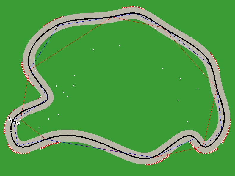
- Generate a set of random points (white dots in Figure 1).
- Get their convex hull (red lines in Figure 1).
- Compute the midpoint of each pair of points in the convex hull and displace it by a random amount.
- Given both a minimum angle and a minimum distance threshold, push apart the set of points resulting from 2 and 3 to try to guarantee that: a) there are not two adjacent points whose distance is less than the minimum distance threshold and b) there is no set of three adjacent points where the angle of the vectors that connect them is less than the minimum angle threshold. (blue lines in Figure 1).
- Obtain the final layout by interpolating all the points obtained after step 4 with splines forcing them to pass through all the input points (black curve in Figure 1).
There are quite a few parameters (more than I would like) that can be modified and tuned to alter the results, and after playing a bit with them I was quite happy with the obtained layouts. Some of them are presented in Figure 2.
Drawing the Racetrack
Since tracks are procedurally generated, the track rendering system has to be generic enough to be able to handle a wide variety of layouts. This made the rendering interesting pretty quickly, and ended up being harder than expected. My results are far from ideal, but anyway, here’s what I came up with. Any suggestions on how to improve it are more than welcome!
Growing the Track
This is the easiest part. To obtain something that begins to look like a racetrack we can simply get a predefined number of evenly spaced points (I chose 1000 points) from the curve obtained at the end of the previous section. Then, at the position of each of these points we simply draw a circle of a given radius (20 pixels in my case).
If the points are close enough there will be no sign of the individual circles and we will have a constant-width racetrack with smooth corners. The result does indeed already look like a racetrack (at least, that is what I like to think). Some results after this stage are presented in the Figure below.

Placing Kerbs
This is where it began to get interesting. My approach is probably not the optimal one, so I am open to give a try at any suggestions on how to improve it.
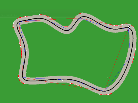
The first thing we have to do is to detect where the corners of the racetrack are. A solution that balances complexity and good results is to use the set of points from which the splines were computed (points connected with blue lines in Figures 1 and 3) to roughly estimate where the corners of the track are.
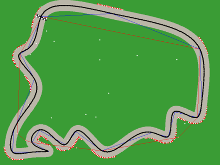
Given three consecutive points we can compute the angle between the two vectors that connect the point in the middle with both extremes. If this angle is inside a range, we add it to the list of corners requiring kerbs. We can play with this range to increase or reduce the amount of kerbs that will be placed in the track. Figures 3 and 4 show results obtained for different angle ranges. One drawback of this approach is that we will miss any corner in the spline which does not satisfy the detection method.
After this step we will have the list of single points, representing a corner in the track, that require kerbs. We have the location of the corner but, before drawing anything, we should know the length of the corner (where does it start and where does it end). To simplify, I decided to set a fixed offset that represents the length of the corner and assume that the points indicating the corner location are the center of the corner. With this approach all the corners will be assumed to have the same length, which is not true but will make our lifes easier.
Now, since we have the guarantee that the points selected in the previous step are part of the spline, we can find their index in the set of points that we used to draw the circles that resulted in the basic racetracks shown in Figure 2. Once having this indices we can, for each corner, build the list of points from the spline that represent the full corner. This list is made by the points inside the range [corner center – offset, corner center + offset]. I had to play a bit with the offset value, but I ended finding a value I was satisfied with.

- Figure 4: Complete racetrack with kerbs. Note that, in this case, not all the dots connected with blue lines have resulted in a corner with a kerb in the final racetrack.
We now have, for each corner, a list of points that indicate its location and length. It is time to draw the kerbs. The main restriction here is that kerbs should outline the corners and be located at the limits of the track. I thought that the best approach would be to draw a simple building block and place it several times along the corner. After a bit of trial and error I ended up with the following tile (althoug it cannot be seen, there is another white stripe at the right):
![]()
Now we just need a position and orientation to place them in the track. Getting the orientation is as simple as computing the angle between the vector obtained from two consecutive points in the corner and the horizontal axis. Instead of two consecutive points I defined yet another offset n and, for each point in the corner, computed the angle between (i, i+n) and the horizontal axis.
As for the location, first we should compute the unitary vector perpendicular to the vector used to determine the orientation. Multiplying this vector by the radius of the circles used to draw the track gives us the displacement from the track center to the place where the kerb should be drawn. With this values we are set to draw the kerb.
To prevent the tiles from ovelapping I repated this process for every 4th (another parameter to be adjusted) point in the list of corner points.
I did the same for the indicator of the track start, but this time placing it in the middle of the track and perpendicular to the track direction. The tile I used is shown below.

Results and Code
The images below show some example racetracks obtained with the algorithm explained above. The code (a bit messy) can be found here.
Results showing the underlying process


Final Racetracks


If you have any doubts or suggestions, do not hesitate to leave a comment below!
