The series so far:
- Storage 101: Welcome to the Wonderful World of Storage
- Storage 101: The Language of Storage
- Storage 101: Understanding the Hard-Disk Drive
- Storage 101: Understanding the NAND Flash Solid State Drive
- Storage 101: Data Center Storage Configurations
- Storage 101: Modern Storage Technologies
- Storage 101: Convergence and Composability
- Storage 101: Cloud Storage
- Storage 101: Data Security and Privacy
- Storage 101: The Future of Storage
- Storage 101: Monitoring storage metrics
- Storage 101: RAID
The storage solutions used by today’s organizations contain hard disk drives (HDDs), solid-state drives (SSDs), or a combination of both to support their various workloads. Organizations might also use tape drives for backup and archiving purposes, but it’s the HDDs and SSDs that keep their applications going. Even if they’ve implemented platforms such as private clouds or hyperconverged infrastructures (HCIs), they still rely on HDDs and SSDs to store their data.
The HDD has long been the workhorse of enterprise data centers, with SSDs making steady inroads as prices have dropped and capacities grown. Yet the HDD remains a major player, not only in data centers, but also in edge environments such as branch and satellite offices.
In the first two articles in this series, I introduced you to a variety of storage-related concepts, most of which were relevant to the HDD. However, I held off discussing the HDD’s internal structure, a discussion I saved for this article. Here I describe the basic components that go into an HDD and how data is stored and accessed so you have a better sense of how a drive works. In the next article, I’ll discuss SSDs in more detail, but for now, we’ll focus exclusively on the HDD.
Introducing the HDD
An HDD is a non-volatile data storage device that can be installed inside a computer or in an external unit such as a standalone box or storage array. The HDD uses electromagnetic technologies to persist digital data to multiple storage platters, or disks, which are enclosed in protective casing and controlled by a logic board. Because an HDD is non-volatile, it can maintain the stored data even if disconnected from power, unlike the memory in most computers, which loses its data as soon as the power stops flowing.
Various types of software can interface with an HDD in order to read and write data. For example, an operating system (OS) can store system and configuration files on an HDD, as well as user-specific data, and a software program can store application files, configuration data, user settings, or user-generated files.
The storage device might communicate with the software via a direct connection between the device and the computer running the software. If the storage device is not directly connected to the computer, communication occurs over a network, which might be shared with other traffic or dedicated specifically to storage.
As discussed in the first article in this series, HDDs conform to specific interfaces and form factors to facilitate connectivity with other systems. For example, an internal HDD might have a 3.5-inch form factor and use the Serial Advanced Technology Attachment (SATA) interface to connect to the computer’s system bus. HDDs also use protocols such as the Internet Small Computer System Interface (iSCSI) to carry out storage-related communications.
Although HDDs vary in terms of capacity and performance, they generally consist of the same basic components: platters, a spindle assembly, an actuator assembly, the casing that houses these components, and a logic board that controls operations. The rest of the article focuses on each of these components.
The HDD platters
Enterprise HDDs include multiple platters that rotate at very rapid speeds, with some clocking in at 15,000 RPMs. The platters are rigid, circular disks stacked on top of each other, with spacers between them to prevent the disks from rubbing together and to accommodate the actuator arms and their read/write heads. Figure 1 illustrates how the platters are stacked on top of each other, with a spindle at their center. The spindle holds them together and rotates them as a single unit.
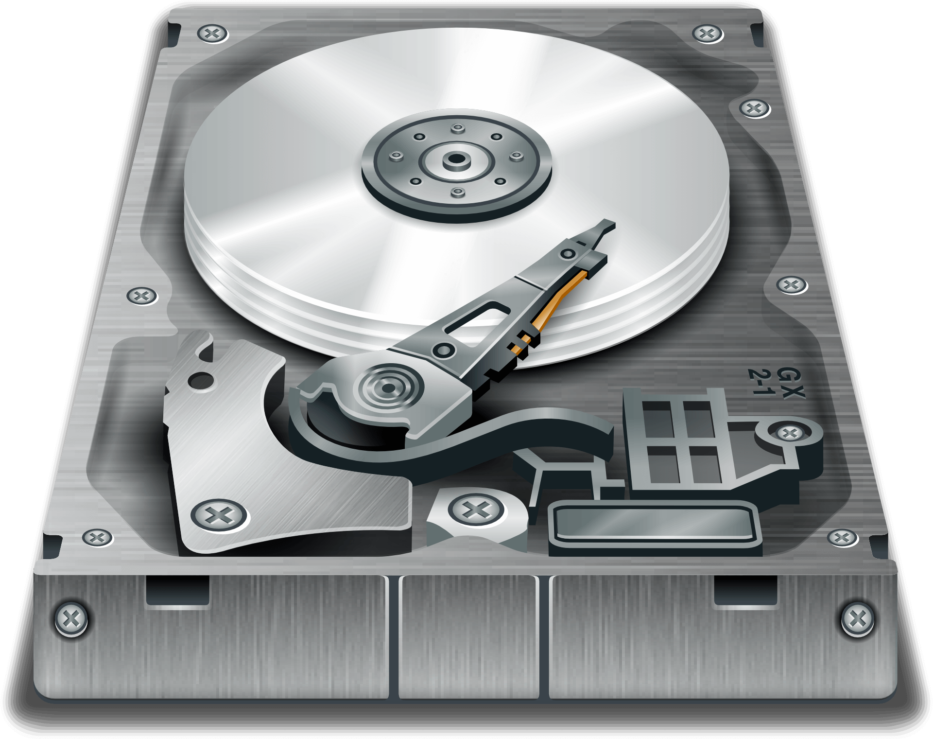
Figure 1. HDD basic components (image by OpenClipart-Vectors)
In this case, the figure shows only one actuator arm, which reaches out over the top platter. In actuality, an HDD also includes arms between the platters. The arms are part of the actuator mechanism, represented in the figure by the components near the bottom of the drive, where the arm articulates at its base. You can get a better sense of this in Figure 2, which shows a set of platters and, if you look closely, the actuator arms reaching in between the platters. (I’ll go more into the actuator mechanism in just a bit.)
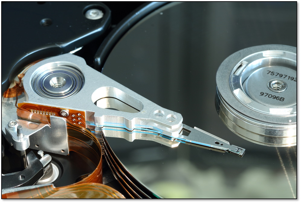
Figure 2. HDD platters and actuator arms (photo by olafpictures)
The photo in Figure 2 should also give you a better idea of what platters look like. As you can see, the platters are formed into thin round disks, which are manufactured with an exacting precision to ensure they’re flat and balanced and that all platters are uniform.
Each platter consists of multiple layers. At its core is a rigid substrate made up of nonmagnetic material such as glass, ceramic, or an aluminum alloy. Vendors are increasingly turning to glass and ceramic—often a glass-ceramic composite—to create the substrate. These materials are more resistant to temperature fluctuations and cracking, making it possible to create thinner platters and support greater densities.
Each side of the platter’s substrate is covered in an extremely thin magnetic layer, which is where the binary data is stored. Vendors use different materials and processes to apply the magnetic media, but always with the goal of maximizing data density while ensuring reliability. A full discussion of these methodologies is beyond the scope of this article. Just know that these are very sophisticated technologies that are continually being refined.
Regardless of how the magnetic media is applied, this layer is incredibly thin, as little as 20 nanometers (nm) or less, which makes the layer quite susceptible to damage. For this reason, a protective coating covers the magnetic media to help mitigate potential harm.
The HDD Spindle Assembly
Running through the center of the platters is a rod, or axel, that serves as the HDD’s spindle. Each platter is securely fixed to the spindle to avoid slippage and ensure that the platters rotate together at a consistent speed. Figure 3 shows that top of the spindle, along with the top platter and its actuator arm.
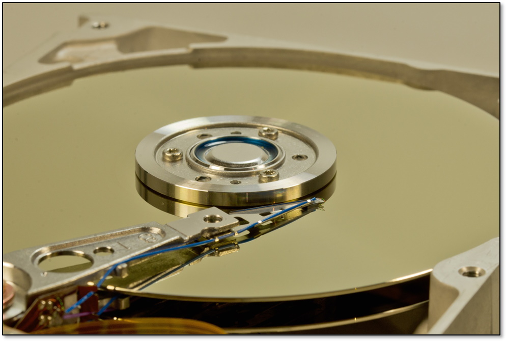
Figure 3. Top of HDD spindle assembly and platter stack (photo by blickpixel)
The spindle is directly attached to a motor that rotates the spindle and platters and controls their speed. The motor is a carefully engineered piece of machinery built to deliver reliable and consistent RPMs throughout the drive’s lifetime while operating with minimal vibration and noise. Contemporary HDDs are available at 4,200, 7,200, 10,000, and 15,000 RPM (often referred to as 4K, 7K, 10K, and 15K, respectively).
An HDD is also described in terms of its form factor, which refers to the size and shape of the storage device. Today’s HDDs are either 2.5-inch or 3.5-inch, with capacities up to 40 TB. Larger, slower drives are typically used for archival use. Faster drives with smaller capacities tend to support applications with higher performance requirements.
Another consideration when evaluating storage is aerial density—the number of bits that can be stored in a specific unit of space on a disk. A higher aerial density means that less physical space is required to store a specific amount of data, resulting in higher throughput.
The HDD Actuator Assembly
The actuator assembly is responsible for writing data to and reading data from the platters. The assembly is made up of two main components: the actuator itself and the set of arms that move across the spinning platters.
Figure 4 shows an example of an actuator assembly, with the top arm clearly visible above the upper platter. A flexible ribbon cable connects the assembly to the HDD’s logic board to manage the reading and writing processes.
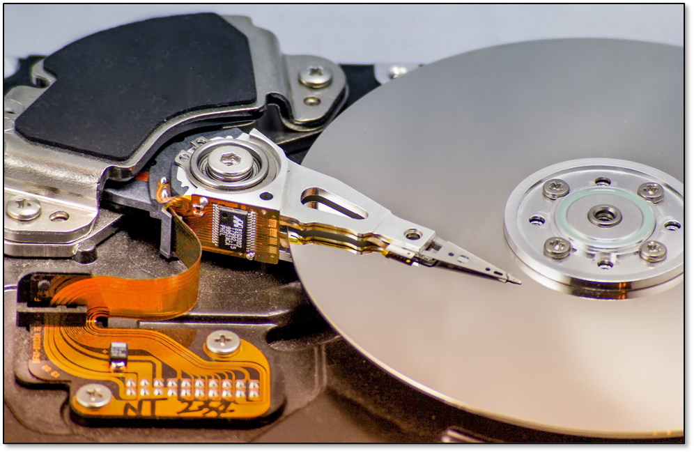
Figure 4. HDD actuator assembly (photo by analogicus)
The actuator is a type of motor whose sole purpose is to control the movement of the arms. The technology on which the actuator is based has evolved significantly over the years as demands on the HDD have increased. Today’s HDDs favor the voice coil design, which incorporates magnets and spring-loaded coils to move the arms across the platters as they spin.
The arms attach directly to the actuator and move as a single unit, traveling in an arc to ensure that they cover all areas available for storage.
There is one arm for each side of each platter. At the end of each arm is a slider that holds the read/write head in place and supports the electrical connection between the head and the drive’s logic board. The slider has an aerodynamic design that enables the head to float above the platter when it is spinning. Figure 5 shows a close-up view of a slider at the end of an arm and the wire that connects the logic board to the head.
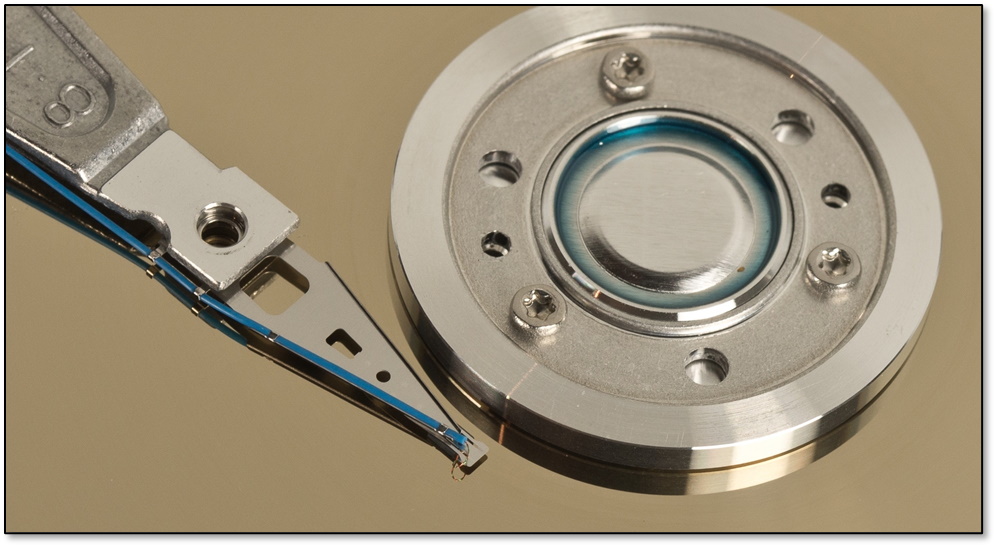
Figure 5. HDD actuator arm and slider (photo by blickpixel)
The read/write head at the tip of the slider is a tiny electromagnetic device that essentially flies over the spinning platter at a very close distance. The head serves as an interface between the HDD’s logic board and platter’s magnetic media.
Back in 2008, Matthieu Lamelot wrote a piece about Seagate drives that appears on the Tom’s Hardware site. In the article, Lamelot came up with a great analogy for describing the read/write head:
With a width of less than a hundred nanometers and a thickness of about ten, it flies above the platter at a speed of up to 15,000 RPM, at a height that’s the equivalent of 40 atoms. If you start multiplying these infinitesimally small numbers, you begin to get an idea of their significance.
Lamelot then compares the head/platter operation to a Boeing 747 flying over the surface of the earth at Mach 800 at less than one centimeter from the ground, while counting every blade of grass and “making fewer than 10 unrecoverable counting errors in an area equivalent to all of Ireland.”
As the platter spins, the head can detect or modify the platter’s magnetic polarities, which represent the individual data bits (1s and 0s).
When data is written to the platter, the HDD’s logic board sends small electrical pulses to the head. The direction of the electrical current determines the magnetic direction, which in turn determines whether a bit is written as a 1 or 0.
Data is organized on the platter in tracks and sectors. Tracks are concentric circles that contain all the data on the platter, providing a logical structure for organizing the data across the magnetic media. Each track is broken into smaller sections referred to as sectors, which are the platter’s smallest storage units. A sector is typically 512 bytes, although some of today’s newer HDDs support larger sectors.
The HDD Casing and Logic Board
The platters, spindle assembly, and actuator assembly are enclosed in a sealed casing to prevent contaminants from getting inside and disrupting storage operations. In some HDDs, the casing includes a filtered vent hole to equalize air pressure when the platters are spinning. Figure 6 shows an HDD in its casing, but with the lid off, something that should never be done outside a highly controlled environment (unless the drive is ready to be recycled).
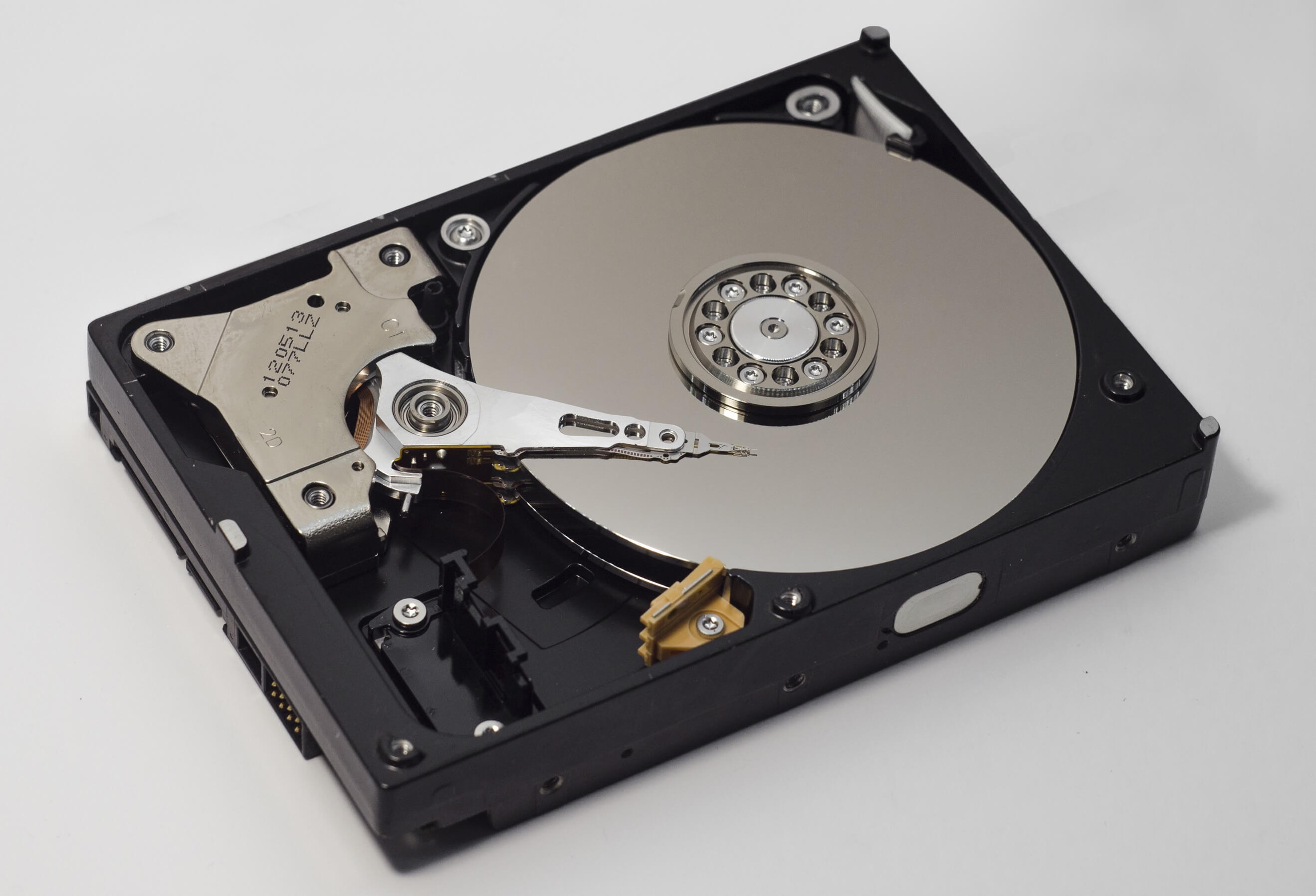
Figure 6. HDD casing and internal components (photo by Plagiator)
Some vendors have introduced helium-filled HDDs, which promise to improve density and performance. Not surprisingly, the casing for these drives is completely sealed and includes no vent hole. Helium is lighter and cooler than air and not as dense, resulting in less friction and lower energy use. Because of this, you can use thinner platters and squeeze more data on each platter.
In addition to the other components, an HDD includes a logic board (circuit board) mounted on the bottom of the casing. The logic board controls all of the HDD’s operations, including the spindle motor, actuator motor, and flow of data to and from the platters. Figure 7 shows part of a logic board with the bottom of the spindle motor visible.
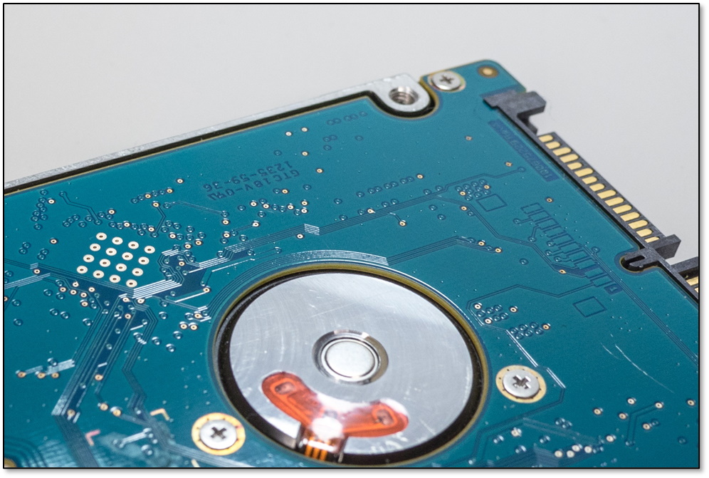
Figure 7. Partial view of HDD logic board (photo by blickpixel)
A logic board typically includes a large circuit referred to as the controller. It also includes a random-access memory (ROM) chip with firmware installed. The controller uses the firmware to manage HDD operations. In most cases, the logic board also contains a random-access memory (RAM) component—often referred to as buffered memory—to improve I/O performance.
The Die-Hard HDD
Not surprisingly, there is much more to each HDD component than what I’ve discussed here. The magnetic media alone could justify an entire series of articles. Even so, the information I’ve covered should help you better understand how the HDD works—or at least start to understand how it works—which in turn should provide you with a better foundation for planning your storage strategies.
Storage media is, of course, much more complex than the simple explanations I’ve provided here, and it’s up to you to decide how far you want to dig into the underlying technologies to make better sense of them. To this end, you can think of this article as a jumping-off point for gaining insight into the HDDs basic components—the platters, spindle assembly, actuator assembly, casing, and logic board—all of which work together to provide non-volatile storage for your digital data.

Load comments