
OpenCV is a powerful tool for doing intensive operations in real-time, even for resource-limited mobile devices. Throughout a couple of tutorials, we’re going to create an Android app that applies various effects to images.
In part 1 of the series, we discussed horizontal and vertical image stitching:
This tutorial will explore creating a cartoon image effect by reducing the number of colors representing the image using lookup tables (LUTs). The sections covered in this tutorial are as follows:
- What is LUT?
- OpenCV Built-in LUTs.
- Color Reduction using LUT for Gray Images.
- Color Reduction using LUT for Color Images.
- Using a Single LUT for All Color Image Channels.
- Using a Single LUT for each Color Image Channel.
- Adaptive Thresholding.
- Noise Removal using Median Filter.
- Cartoon Effect.
- Building Android App.
The source code of this tutorial is available in this GitHub project.
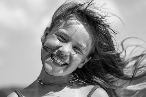
The following image will be used in the experiments.

Let’s get started.
What is LUT?
When talking about images, a lookup table (or LUT for short) is a mapping from one set of colors to another set of colors. One use of LUTs in image processing is to change the colors that will be displayed in a given image. Let’s explain it with an example.
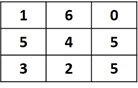
Let’s say the following 3×3 array represents an image. If each pixel is represented as 3 bits, then the range of pixel values is from 0 to 7.

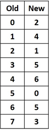
If, for a given reason, we are to change the colors by which the previous image is displayed, how can we make that change? One method is using a LUT such as the one shown below. It works by mapping each old pixel value in the previous image to its new value. According to the below LUT, each pixel in the old image with value 0 will get replaced by the new value 2. Each pixel with value 4 will be replaced by value 6.
In order for the LUT to work with all pixel values within the image, the LUT must have a number of entries that are equal to the number of colors existing in the image. For the above image, it’s represented as 3 and a total of 8 colors. Thus, the LUT must include 8 entries, one for each color. If there’s a gray image represented by 8 bits—that is, there are 256 colors—then the LUT must have 256 entries.
By applying the LUT for all image pixels, the new image is given below. Just look at the table to replace each pixel with the new value. This is why it’s called a lookup table.
OpenCV Built-in LUTs
In OpenCV, there are a number of LUTs for changing the colors used for displaying an image. The method Imgproc.applyColorMap() is used to apply the LUT over an image. Note that a LUT can also be called a colormap. This method accepts 3 arguments:
- Mat src: Source Mat to change its colors.
- Mat dst: Destination Mat that receives the result.
- int colormap: Integer representing the colormap used for changing the colors.
There are different colormaps in OpenCV such as autumn, summer, winter, pink, rainbow, and more. The code below is used for applying the summer colormap over the image used in the tutorial. Note that the summer colormap has a value 6 for the third integer argument. But we can use Imgproc.COLORMAP_SUMMER, which is a constant with value 6.
The result is given in the next figure.
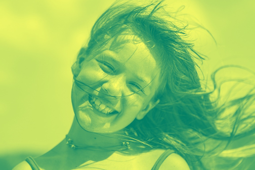
The next figure represents the scale of colors for the summer color. The color on the left side is green, which means that the dark pixels in the image will be replaced by green colors. As the color brightens, the color will move from green to dark yellow. The sky in the image used in this tutorial has bright colors, and thus the new image is taking from the yellow color more than the green color. Let’s discuss another colormap.

The below example uses the pink colormap. The result is shown in the next figure. To explain why the image appears this way, let’s look at the color scale of the pink colormap. The third argument is set to Imgproc.COLORMAP_PINK, which is a constant with value 10.

The scale of colors for this colormap is shown below. On the left side, there’s a black, which means that the dark pixels in the original image will be replaced by a dark color. As the color is brightens, the colormap moves to a brighter color until reaching white.

In order to understand how the colormaps or LUTs are created, let’s create our own color map.
Color Reduction using LUT for Gray Images
Before we start working with color images, let’s start with the simplest case, in which a LUT is created for a gray image. A gray image is usually represented as 8 bits. As a result, there are 256 color levels ranging from 0 to 255. In order to create a LUT, it must have 256 elements.
The first element in the LUT defines the new color for the first level in the gray image (0), the second LUT element is associated with level 1, and so on. So in order to create a LUT, just think of creating a Mat array with 256 elements.
The line of code below creates a Mat of zeros. The size of this Mat is 1×256 because the gray image has 256 colors. The type of this mat is set to 8UC1, which means the value in each element is an unsigned integer represented in 8 bits.
Thus, the acceptable values for each element are the integers from 0 to 255. If a value is below 0, it will be clipped at 0. The same happens for values over 255, as they’re returned back to 255.
Note that the above Mat could be used as a LUT without any problem, but the resulting image will be all zeros because all 256 colors in the gray image will be associated with the value 0 in the LUT. We should add different values in the LUT. This can be simply done with for loops that assign a number of different values to the LUT. The code is given below.
The number of different colors in the LUT is defined in the numColors variable. The first for loop assigns the unique values for the zeros Mat created previously. It uses a step equal to 256/numColors.
This guarantees that the outer loop creates a number of colors equal to what is specified in the numColors variable. When numColors is set to 5, then the step is 256/5=51.2. Thus, the values of the loop variable x will be 51.2, 102.4, 153.4, 204.8, and 256.2.
int numColors = 5;

int startIdx = 0;
for (int x = 0; x < 256; x += 256.0 / numColors) {
    lookupTable.put(x, 0, x);

    for (int y = startIdx; y < x; y++) {
        if (lookupTable.get(y, 0)[0] == 0) {
            lookupTable.put(y, 0, lookupTable.get(x, 0));
            System.out.println(lookupTable.get(x, 0)[0]);
        }
    }
    startIdx = x;
}
Because the type of the lookupTable Mat is 8UC1, then all of these float numbers will be converted into integers by removing the decimal. That is, 51.2 will be 51 and 204.8 will be 204. Regarding the value 256.2, which exceeds the maximum acceptable value for the type 8UC1, it will be clipped at 255. Thus, the unique values in the Mat are 51, 102, 154, 204, and 255.
The indices in which these elements are added are equal to their values. That is, the value of the Mat element at index 51 is 51, the value at index 102 is 102, and so on.
The outer loop sets 5 elements to these values. All other elements in the LUT are zeros as initialized at the time of creating the lookupTable Mat. The inner loop works by filling these zeros. The elements from index 0 to the index of the first unique element (51), are all set to 51. The elements starting from index 51 to 102 are set to 102, the elements from index 102 to 154 are set to 154, and so on. The result is a Mat in which there are only 5 unique values representing all the 256 elements in the LUT.
In order to reuse the above code, a method named createLUT() is created and listed below. It accepts the number of colors. It checks that the number of colors is between 0 and 256 (inclusive). It returns a Mat representing the LUT.
Mat createLUT(int numColors) {
    // When numColors=1 the LUT will only have 1 color which is black.
    if (numColors < 0 || numColors > 256) {
        System.out.println("Invalid Number of Colors. It must be between 0 and 256 inclusive.");
        return null;
    }

    Mat lookupTable = Mat.zeros(new Size(1, 256), CV_8UC1);

    int startIdx = 0;
    for (int x = 0; x < 256; x += 256.0 / numColors) {
        lookupTable.put(x, 0, x);

        for (int y = startIdx; y < x; y++) {
            if (lookupTable.get(y, 0)[0] == 0) {
                lookupTable.put(y, 0, lookupTable.get(x, 0));
            }
        }
        startIdx = x;
    }
    return lookupTable;
}
After preparing the LUT, the next step is to apply it over the image. This is done using the LUT() method available in the Core class. It accepts 3 arguments which are:
1. Mat src: Source Mat.
2. Mat lut: LUT
3. Mat dst: Destination to save the result.
After preparing the LUT and understanding how to apply it to the image, next we need to apply it to a gray image. The following code does the following:
- Reads an image.
- Converts the image from BGR to gray.
- Saves the original image file.
- Creates the LUT as discussed previously.
- Applies the LUT over the image using the LUT() method.
- Saves the result of applying the LUT.
The image is converted from BGR to gray using the cvtColor() method available in the Imgproc class. It accepts 3 arguments, which are the source, destination, and an integer representing the conversion code. The code for the conversion from BGR to gray is 6. We can also use Imgproc.COLOR_BGR2GRAY, which is a constant with value 6.
Mat img1 = Imgcodecs.imread("img.jpg");
Imgproc.cvtColor(img1, img1, Imgproc.COLOR_BGR2GRAY);
Imgcodecs.imwrite("originalImage.jpg", result);

int numColors = 5;

Mat lookupTable = createLUT(numColors);

LUT(img, lookupTable, img);

Imgcodecs.imwrite("redueColor.jpg", img);
We can also create a method named reduceColorsGray() for combining the above code, as shown below. It accepts the image to which the LUT will be applied in addition to the number of colors. This method returns the Mat after applying the LUT.
Mat reduceColorsGray(Mat img, int numColors) {
    Mat LUT = createLUT(numColors);

    LUT(img, LUT, img);

    return img;
}
By simply calling the reduceColorsGray() method, the LUT will be created and applied to the image, and the result is returned. Here’s an example:
Mat img1 = Imgcodecs.imread("img.jpg");
Imgproc.cvtColor(img1, img1, Imgproc.COLOR_BGR2GRAY);
Imgcodecs.imwrite("originalImage.jpg", result);

Mat result = reduceColorsGray(img, 5)
Imgcodecs.imwrite("redueColor.jpg", result);
The original image after being converted into a gray image is shown below.
The result image from applying a LUT with 5 colors over the above gray image is shown below.

In order to convert the image into binary, just use 2 colors only in the LUT. The result is given below. Note that setting the number of colors to 0 or 1 returns a black image.

By increasing the number of colors, the image that results from applying the LUT approaches the input gray image. The next figure shows the result of using 20 colors.

Here is the result after using 50 colors:

It’s expected that creating a LUT with 256 colors will return the original gray image. This is shown below. There’s no difference between the image before and after applying the LUT.
At this point, we’ve successfully applied a LUT to a gray image by specifying the number of unique colors. The next section discusses applying a LUT to a color image.
Color Reduction Using LUT for Color Images
Applying the LUT to a color image is not so different from applying it to just a gray image because a color image actually consists of a number of gray images. For applying LUT over color images, there are 2 techniques:
- Using a single LUT for all color image channels.
- Using a single LUT for each color channel.
Let’s discuss these 2 approaches.
Using a Single LUT for All Color Image Channels
The first approach is to just prepare a single LUT and apply it over the color image. In this case, the single LUT will be applied to all image channels. Compared to the previous code for applying the LUT over a gray image, the only change is to remove the line that converts the image into gray and leave a color image as it is. The code is listed below.
Mat img1 = Imgcodecs.imread("img.jpg");

int numColors = 5;

Mat lookupTable = createLUT(numColors);

LUT(img, lookupTable, img);

Imgcodecs.imwrite("redueColor.jpg", img);
The previous code uses just 5 colors in the LUT. Note that such LUT is identical to the one created previously. That is, the 5 unique values are 51, 102, 154, 204, and 255. A LUT with these 5 values is applied to the 3 channels (red, green, and blue). As such, each of the 3 channels will have 5 unique gray levels.
If each channel has 5 gray levels, then the total number of colors produced by such levels is 5x5x5=125. Thus, the color image produced by applying the LUT will have 125 unique colors. The resulting image from the above code is shown below.

As the number of colors increases, the image tends to be more similar to the original color image. The next figure shows the result after using 15 colors building the LUT. When the number of colors is set to 256, the original image will be reproduced. Setting the number of colors to 0 or 1 returns a black image.

After applying a single LUT to all color image channels, the next section creates a LUT for each channel. If there are 3 channels, for example, there will be 3 LUTs—one for each channel.
Using a Single LUT for Each Color Channel
Because we’re looking to create a LUT for each channel, then the LUT for the 3 channels are created as shown below. The number of colors for all channels is set to 5.
int numRed = 5;
Mat redLUT = createLUT(numRed);

int numGreen = 5;
Mat greenLUT = createLUT(numGreen);

int numBlue = 5;
Mat blueLUT = createLUT(numBlue);
After that, we need to split the image into its 3 channels. This is done by creating a Java list that accepts 3 Mat arrays. Using the Core.split() method, the image is split into 3 channels, and these channels are saved in the list.
You can access each element in the list using the get() method after passing the index of the element. For example, BGR.get(0) returns the first channel (the blue one). The code below applies the 3 LUTs to the 3 channels.
Now the BGR list has the 3 channels after applying their associated LUT. The remaining step is to merge these 3 channels again to create a BGR image using the Core.merge() method, according to the line below:
For collecting the above code, a method named reduceColors() is created. It accepts the Mat image to change its colors in addition to the number of colors for each individual channel.
Mat reduceColors(Mat img, int numRed, int numGreen, int numBlue) {
    Mat redLUT = createLUT(numRed);
    Mat greenLUT = createLUT(numGreen);
    Mat blueLUT = createLUT(numBlue);

    List<Mat> BGR = new ArrayList<>(3);
    Core.split(img, BGR);

    LUT(BGR.get(0), blueLUT, BGR.get(0));
    LUT(BGR.get(1), greenLUT, BGR.get(1));
    LUT(BGR.get(2), redLUT, BGR.get(2));

    Core.merge(BGR, img);

    return img;
}
The line below gives an example for calling the above method:
Because the number of colors for all channels are equal, then the result will be identical to applying a single LUT to all of these channels. The result (shown below) is identical to the result achieved previously by using a single LUT for all channels with 5 colors.

The difference appears when using a different number of colors for the different channels. For example, the line below calls the reduceColors() method and passes 50, 0, and 0 for the number of colors for the red, green, and blue channels respectively.
The result is shown below, where the red color is dominating the other colors:

The same effect happens when enlarging the value of 1 channel more than the other 2 channels. For example, the result of executing the next line will be green, as shown in the next figure:

According to the next line, the number of colors for the red and green channels is 50, but it’s 0 for blue. The result will be yellow as given in the next figure. Note that yellow is the color resulted from combining red and green:

Let’s summarize what we’ve discussed so far.
First, we discussed and defined the LUT. Then, we looked at some built-in LUTs in OpenCV and applied them using the applyColorMap() method. After that, we created our own custom LUT, which is just a Mat with 256 elements. Using the LUT() method, we applied the custom LUT to a gray image. After that, we applied a single LUT to a color image. Finally, we applied 3 LUTs to a color image created, with one for each channel.
In order to create a cartoon image, there are 2 additional steps which we’ll discuss in the following sections.
Adaptive Thresholding
A step that helps in achieving the cartoon effect is to convert the image to binary by thresholding it. After the image is converted to gray, the simplest threshold uses a single value to classify the pixels as black or white. The pixels above the threshold are classified as white and the pixels below it are black.
The type of thresholding used in this tutorial is adaptive thresholding because it changes its threshold dynamically when applied to different types of images.
Before applying the adaptive threshold, the image is converted from BGR to GRAY according to the line below, given that img is the original color image.
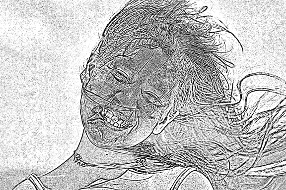
After that, the adaptive threshold can be applied using the adaptiveThreshold() method, as shown below. For information about the arguments, please visit the official documentation here.
The result of the adaptive threshold is shown below. Note that there is much noise in the result. For reducing the noise, it is preferred to filter the gray image before being converted into binary. One type of filter is the median filter.
Noise Removal Using Median Filter
The median filter is a type of smoothing filter that’s supported in OpenCV using the Imgproc.medianBlur() method. It accepts 3 arguments:
- src: Source Mat.
- dst: Destination Mat in which the output will be saved.
- ksize: kernel size.
Here’s an example of calling this method over a gray image. The result is shown in the next figure. The result is smooth and the image is less prone to noise pixels.

After applying the median filter, the image is less noisy, and thus the result of applying the adaptive threshold over the filtered image will be much better (shown below). In order to create the cartoon image, the result of applying the LUT over the color image and the result of the adaptive threshold are combined together.

Cartoon Effect
Now we’ve completed the 3 steps required for creating the cartoon image, which are as follows:
- Reducing image colors
- Noise removal using median filter
- Adaptive thresholding
The next step is to combine them. The complete code for creating the cartoon image is included below. At the end of the code, the image resulting from the reduceColors() method is combined with the image resulting from the adaptiveThreshold() method using the Core.bitwise_and() method.
Note that the result of the adaptiveThreshold() method is a gray image with just 1 channel, but the result of the reduceColors() method is a color image with 3 channels. Before applying the Core.bitwise_and() method, we have to make sure the 2 images the same size. This is why the result of the adaptiveThreshold() method is converted back to a color image before applying the Core.bitwise_and() method.
Mat img1 = Imgcodecs.imread("img.jpg");

Mat reducedColorImage = reduceColors(img1, 80, 80, 80);

Mat result = new Mat();
Imgproc.cvtColor(img1, result, Imgproc.COLOR_BGR2GRAY);

Imgproc.medianBlur(result, result, 15);

Imgproc.adaptiveThreshold(result, result, 255, Imgproc.ADAPTIVE_THRESH_MEAN_C, Imgproc.THRESH_BINARY, 15, 2);

Imgproc.cvtColor(result, result, Imgproc.COLOR_GRAY2BGR);
Core.bitwise_and(reducedColorImage, result, result);
Imgcodecs.imwrite("result.jpg", result);
We can create a method that holds the above code:
Mat cartoon(Mat img, int numRed, int numGreen, int numBlue) {
    Mat reducedColorImage = reduceColors(img, numRed, numGreen, numBlue);

    Mat result = new Mat();
    Imgproc.cvtColor(img, result, Imgproc.COLOR_BGR2GRAY);
    Imgproc.medianBlur(result, result, 15);

    Imgproc.adaptiveThreshold(result, result, 255, Imgproc.ADAPTIVE_THRESH_MEAN_C, Imgproc.THRESH_BINARY, 15, 2);

    Imgproc.cvtColor(result, result, Imgproc.COLOR_GRAY2BGR);

    Core.bitwise_and(reducedColorImage, result, result);

    return result;
}
Here’s an example for using the above method:
The result of running the above code is shown below:

The result will change by changing the parameters passed to the reduceColors() method. For example, using reduceColors(img1, 80, 15, 0) returns the result below.
Note that the pipeline for producing such cartoon images is an art more than an image processing science. So if the current results don’t match your needs, you can add new steps or modify existing steps by using different parameters.

After completing the effect of this tutorial, our next step is to edit the Android app created in the previous tutorial to add this effect.
Building Android App
The activity XML layout is listed below. A new Button is added for each of the effects discussed in this tutorial.
<?xml version="1.0" encoding="utf-8"?>
<LinearLayout xmlns:android="http://schemas.android.com/apk/res/android"
    xmlns:app="http://schemas.android.com/apk/res-auto"
    xmlns:tools="http://schemas.android.com/tools"
    android:layout_width="match_parent"
    android:layout_height="match_parent"
    android:orientation="vertical"
    tools:context=".MainActivity">

    <Button
        android:layout_width="match_parent"
        android:layout_height="wrap_content"
        android:id="@+id/stitchHorizontal"
        android:text="Stitch Images Horizontally"
        android:onClick="stitchHorizontal"/>
    <Button
        android:layout_width="match_parent"
        android:layout_height="wrap_content"
        android:id="@+id/stitchVertical"
        android:text="Stitch Images Vertically"
        android:onClick="stitchVectical"/>
    <Button
        android:layout_width="match_parent"
        android:layout_height="wrap_content"
        android:id="@+id/reduceColors"
        android:text="Reduce Colors"
        android:onClick="reduceImageColors"/>
    <Button
        android:layout_width="match_parent"
        android:layout_height="wrap_content"
        android:id="@+id/reduceColorsGray"
        android:text="Reduce Colors Gray"
        android:onClick="reduceImageColorsGray"/>
    <Button
        android:layout_width="match_parent"
        android:layout_height="wrap_content"
        android:id="@+id/medianFilter"
        android:text="Median Filter"
        android:onClick="medianFilter"/>
    <Button
        android:layout_width="match_parent"
        android:layout_height="wrap_content"
        android:id="@+id/adaptiveThreshold"
        android:text="Adaptive Threshold"
        android:onClick="adaptiveThreshold"/>
    <Button
        android:layout_width="match_parent"
        android:layout_height="wrap_content"
        android:id="@+id/cartoon"
        android:text="Cartoon Image"
        android:onClick="cartoonImage"/>
    <ImageView
        android:layout_width="match_parent"
        android:layout_height="wrap_content"
        android:id="@+id/opencvImg"/>

</LinearLayout>
The interface of the Android app is shown below.

The activity Java code is listed below, which includes all functions discussed previously and the handling of button click events.
package com.example.imageeffectsopencv;

import android.graphics.Bitmap;
import android.graphics.BitmapFactory;
import android.media.MediaScannerConnection;
import android.net.Uri;
import android.os.Bundle;
import android.os.Environment;
import android.support.v7.app.AppCompatActivity;
import android.util.Log;
import android.view.View;
import android.widget.ImageView;

import com.example.imageeffectsopencv.R;

import org.opencv.android.OpenCVLoader;
import org.opencv.android.Utils;
import org.opencv.core.Core;
import org.opencv.core.Mat;
import org.opencv.core.Size;
import org.opencv.imgproc.Imgproc;

import java.io.File;
import java.io.FileOutputStream;
import java.text.SimpleDateFormat;
import java.util.ArrayList;
import java.util.Arrays;
import java.util.Date;
import java.util.List;
import java.util.Locale;

import static org.opencv.core.Core.LUT;
import static org.opencv.core.CvType.CV_8UC1;

public class MainActivity extends AppCompatActivity {

    @Override
    protected void onCreate(Bundle savedInstanceState) {
        super.onCreate(savedInstanceState);
        setContentView(R.layout.activity_main);
        OpenCVLoader.initDebug();
    }

    public void cartoonImage(View view) {
        BitmapFactory.Options options = new BitmapFactory.Options();
        options.inScaled = false; // Leaving it to true enlarges the decoded image size.
        Bitmap original = BitmapFactory.decodeResource(getResources(), R.drawable.part3, options);

        Mat img1 = new Mat();
        Utils.bitmapToMat(original, img1);
        Imgproc.cvtColor(img1, img1, Imgproc.COLOR_BGRA2BGR);

        Mat result = cartoon(img1, 80, 15, 10);

        Bitmap imgBitmap = Bitmap.createBitmap(result.cols(), result.rows(), Bitmap.Config.ARGB_8888);
        Utils.matToBitmap(result, imgBitmap);

        ImageView imageView = findViewById(R.id.opencvImg);
        imageView.setImageBitmap(imgBitmap);
        saveBitmap(imgBitmap, "cartoon");
    }

    public void reduceImageColors(View view){
        BitmapFactory.Options options = new BitmapFactory.Options();
        options.inScaled = false; // Leaving it to true enlarges the decoded image size.
        Bitmap original = BitmapFactory.decodeResource(getResources(), R.drawable.part3, options);

        Mat img1 = new Mat();
        Utils.bitmapToMat(original, img1);

        Mat result = reduceColors(img1, 80, 15, 10);

        Bitmap imgBitmap = Bitmap.createBitmap(result.cols(), result.rows(), Bitmap.Config.ARGB_8888);
        Utils.matToBitmap(result, imgBitmap);

        ImageView imageView = findViewById(R.id.opencvImg);
        imageView.setImageBitmap(imgBitmap);
        saveBitmap(imgBitmap, "reduce_colors");
    }

    public void reduceImageColorsGray(View view){
        BitmapFactory.Options options = new BitmapFactory.Options();
        options.inScaled = false; // Leaving it to true enlarges the decoded image size.
        Bitmap original = BitmapFactory.decodeResource(getResources(), R.drawable.part3, options);

        Mat img1 = new Mat();
        Utils.bitmapToMat(original, img1);

        Imgproc.cvtColor(img1, img1, Imgproc.COLOR_BGR2GRAY);
        Mat result = reduceColorsGray(img1, 5);

        Bitmap imgBitmap = Bitmap.createBitmap(result.cols(), result.rows(), Bitmap.Config.ARGB_8888);
        Utils.matToBitmap(result, imgBitmap);

        ImageView imageView = findViewById(R.id.opencvImg);
        imageView.setImageBitmap(imgBitmap);
        saveBitmap(imgBitmap, "reduce_colors_gray");
    }

    public void medianFilter(View view) {
        BitmapFactory.Options options = new BitmapFactory.Options();
        options.inScaled = false; // Leaving it to true enlarges the decoded image size.
        Bitmap original = BitmapFactory.decodeResource(getResources(), R.drawable.part3, options);

        Mat img1 = new Mat();
        Utils.bitmapToMat(original, img1);
        Mat medianFilter = new Mat();
        Imgproc.cvtColor(img1, medianFilter, Imgproc.COLOR_BGR2GRAY);

        Imgproc.medianBlur(medianFilter, medianFilter, 15);

        Bitmap imgBitmap = Bitmap.createBitmap(medianFilter.cols(), medianFilter.rows(), Bitmap.Config.ARGB_8888);
        Utils.matToBitmap(medianFilter, imgBitmap);

        ImageView imageView = findViewById(R.id.opencvImg);
        imageView.setImageBitmap(imgBitmap);
        saveBitmap(imgBitmap, "median_filter");
    }

    public void adaptiveThreshold(View view) {
        BitmapFactory.Options options = new BitmapFactory.Options();
        options.inScaled = false; // Leaving it to true enlarges the decoded image size.
        Bitmap original = BitmapFactory.decodeResource(getResources(), R.drawable.part3, options);

        Mat adaptiveTh = new Mat();
        Utils.bitmapToMat(original, adaptiveTh);
        Imgproc.cvtColor(adaptiveTh, adaptiveTh, Imgproc.COLOR_BGR2GRAY);

        Imgproc.medianBlur(adaptiveTh, adaptiveTh, 15);

        Imgproc.adaptiveThreshold(adaptiveTh, adaptiveTh, 255, Imgproc.ADAPTIVE_THRESH_MEAN_C, Imgproc.THRESH_BINARY, 9, 2);

        Bitmap imgBitmap = Bitmap.createBitmap(adaptiveTh.cols(), adaptiveTh.rows(), Bitmap.Config.ARGB_8888);
        Utils.matToBitmap(adaptiveTh, imgBitmap);

        ImageView imageView = findViewById(R.id.opencvImg);
        imageView.setImageBitmap(imgBitmap);
        saveBitmap(imgBitmap, "adaptive_threshold");
    }

    public void stitchVectical(View view){
        BitmapFactory.Options options = new BitmapFactory.Options();
        options.inScaled = false; // Leaving it to true enlarges the decoded image size.
        Bitmap im1 = BitmapFactory.decodeResource(getResources(), R.drawable.part1, options);
        Bitmap im2 = BitmapFactory.decodeResource(getResources(), R.drawable.part2, options);
        Bitmap im3 = BitmapFactory.decodeResource(getResources(), R.drawable.part3, options);

        Mat img1 = new Mat();
        Mat img2 = new Mat();
        Mat img3 = new Mat();
        Utils.bitmapToMat(im1, img1);
        Utils.bitmapToMat(im2, img2);
        Utils.bitmapToMat(im3, img3);

        Bitmap imgBitmap = stitchImagesVectical(Arrays.asList(img1, img2, img3));
        ImageView imageView = findViewById(R.id.opencvImg);
        imageView.setImageBitmap(imgBitmap);
        saveBitmap(imgBitmap, "stitch_vectical");
    }

    public void stitchHorizontal(View view){
        BitmapFactory.Options options = new BitmapFactory.Options();
        options.inScaled = false; // Leaving it to true enlarges the decoded image size.
        Bitmap im1 = BitmapFactory.decodeResource(getResources(), R.drawable.part1, options);
        Bitmap im2 = BitmapFactory.decodeResource(getResources(), R.drawable.part2, options);
        Bitmap im3 = BitmapFactory.decodeResource(getResources(), R.drawable.part3, options);

        Mat img1 = new Mat();
        Mat img2 = new Mat();
        Mat img3 = new Mat();
        Utils.bitmapToMat(im1, img1);
        Utils.bitmapToMat(im2, img2);
        Utils.bitmapToMat(im3, img3);

        Bitmap imgBitmap = stitchImagesHorizontal(Arrays.asList(img1, img2, img3));
        ImageView imageView = findViewById(R.id.opencvImg);
        imageView.setImageBitmap(imgBitmap);
        saveBitmap(imgBitmap, "stitch_horizontal");
    }

    Mat cartoon(Mat img, int numRed, int numGreen, int numBlue) {
        Mat reducedColorImage = reduceColors(img, numRed, numGreen, numBlue);

        Mat result = new Mat();
        Imgproc.cvtColor(img, result, Imgproc.COLOR_BGR2GRAY);
        Imgproc.medianBlur(result, result, 15);

        Imgproc.adaptiveThreshold(result, result, 255, Imgproc.ADAPTIVE_THRESH_MEAN_C, Imgproc.THRESH_BINARY, 15, 2);

        Imgproc.cvtColor(result, result, Imgproc.COLOR_GRAY2BGR);

        Log.d("PPP", result.height() + " " + result.width() + " " + reducedColorImage.type() + " " + result.channels());
        Log.d("PPP", reducedColorImage.height() + " " + reducedColorImage.width() + " " + reducedColorImage.type() + " " + reducedColorImage.channels());

        Core.bitwise_and(reducedColorImage, result, result);

        return result;
    }

    Mat reduceColors(Mat img, int numRed, int numGreen, int numBlue) {
        Mat redLUT = createLUT(numRed);
        Mat greenLUT = createLUT(numGreen);
        Mat blueLUT = createLUT(numBlue);

        List<Mat> BGR = new ArrayList<>(3);
        Core.split(img, BGR); // splits the image into its channels in the List of Mat arrays.

        LUT(BGR.get(0), blueLUT, BGR.get(0));
        LUT(BGR.get(1), greenLUT, BGR.get(1));
        LUT(BGR.get(2), redLUT, BGR.get(2));

        Core.merge(BGR, img);

        return img;
    }

    Mat reduceColorsGray(Mat img, int numColors) {
        Mat LUT = createLUT(numColors);

        LUT(img, LUT, img);

        return img;
    }

    Mat createLUT(int numColors) {
        // When numColors=1 the LUT will only have 1 color which is black.
        if (numColors < 0 || numColors > 256) {
            System.out.println("Invalid Number of Colors. It must be between 0 and 256 inclusive.");
            return null;
        }

        Mat lookupTable = Mat.zeros(new Size(1, 256), CV_8UC1);

        int startIdx = 0;
        for (int x = 0; x < 256; x += 256.0 / numColors) {
            lookupTable.put(x, 0, x);

            for (int y = startIdx; y < x; y++) {
                if (lookupTable.get(y, 0)[0] == 0) {
                    lookupTable.put(y, 0, lookupTable.get(x, 0));
                }
            }
            startIdx = x;
        }
        return lookupTable;
    }

    Bitmap stitchImagesVectical(List<Mat> src) {
        Mat dst = new Mat();
        Core.vconcat(src, dst); //Core.hconcat(src, dst);
        Bitmap imgBitmap = Bitmap.createBitmap(dst.cols(), dst.rows(), Bitmap.Config.ARGB_8888);
        Utils.matToBitmap(dst, imgBitmap);

        return imgBitmap;
    }

    Bitmap stitchImagesHorizontal(List<Mat> src) {
        Mat dst = new Mat();
        Core.hconcat(src, dst); //Core.vconcat(src, dst);
        Bitmap imgBitmap = Bitmap.createBitmap(dst.cols(), dst.rows(), Bitmap.Config.ARGB_8888);
        Utils.matToBitmap(dst, imgBitmap);

        return imgBitmap;
    }

    public void saveBitmap(Bitmap imgBitmap, String fileNameOpening){
        SimpleDateFormat formatter = new SimpleDateFormat("yyyy_MM_dd_HH_mm_ss", Locale.US);
        Date now = new Date();
        String fileName = fileNameOpening + "_" + formatter.format(now) + ".jpg";

        FileOutputStream outStream;
        try{
            // Get a public path on the device storage for saving the file. Note that the word external does not mean the file is saved in the SD card. It is still saved in the internal storage.
            File path = Environment.getExternalStoragePublicDirectory(Environment.DIRECTORY_PICTURES);

            // Creates directory for saving the image.
            File saveDir =  new File(path + "/HeartBeat/");

            // If the directory is not created, create it.
            if(!saveDir.exists())
                saveDir.mkdirs();

            // Create the image file within the directory.
            File fileDir =  new File(saveDir, fileName); // Creates the file.

            // Write into the image file by the BitMap content.
            outStream = new FileOutputStream(fileDir);
            imgBitmap.compress(Bitmap.CompressFormat.JPEG, 100, outStream);

            MediaScannerConnection.scanFile(this.getApplicationContext(),
                    new String[] { fileDir.toString() }, null,
                    new MediaScannerConnection.OnScanCompletedListener() {
                        public void onScanCompleted(String path, Uri uri) {
                        }
                    });

            // Close the output stream.
            outStream.close();
        }catch(Exception e){
            e.printStackTrace();
        }
    }
}
After clicking on the “Cartoon Image” button, the resource image is converted into a cartoon image as shown in the next figure.


Conclusion
This tutorial, which is part 2 of the image effects using OpenCV for Android series, discussed a new image effect for creating cartoon images from color images. The main idea is to reduce the number of colors used for representing the image. The reduced color image is then combined with a binary image created using adaptive thresholding after being filtered using the median filter, which is used to remove noise.
In the next tutorial in the series, we’ll look at image transparency in OpenCV —adding an alpha channel to the color space and manipulating it to merge different images together.

Comments 0 Responses