
For those of who manage multiple network-attached devices, website or servers, it's important to know when they are down as soon as possible.
Whether you are responsible for keeping a website up, a file server running smoothly, or if you just want to know if your home router goes down, microcontrollers are making it even easier for people to build monitoring solutions.
Recently, I dove into the world of the Internet of Things to develop a simple alarm device which checks a pre-defined IP Address / DNS name every 5 seconds and sounds an alarm if the host does not reply to ping.
Its the kind of project which can be easily put together with a fantastic, inexpensive microcontroller called the ESP8266 and I am going to show you how you can build one of these yourself to monitor your servers, websites or even your smart fridge.
What Do I Need?
An ESP8266

This is the NodeMCU version of the EDP8266 which is the version I used to build this device.
The ESP8266 is an amazing (and very cheap at roughly $6 dollars) piece of equipment.
It is a WiFi microchip that is able to exploit the full TCP/IP stack. Whats more, it's a microcontroller, so you can program it in the same what you would an Arduino Uno or Arduino Mega controller board.
This means that with just this board, a breadboard, a few jumper wires and an active buzzer, we have the hardware we need to build our alarm.
I'll quickly go over how we connect this to the rest of our hardware so that we can get to the code.
Boards and Wires and Buzzers Oh My!
This guide is mostly about the code we're writing to develop the network monitoring functionality, so a basic familiarity with circuits is assumed. However the diagram below should be enough to show you how to build a circuit for the ESP8266 and a buzzer on a breadboard.
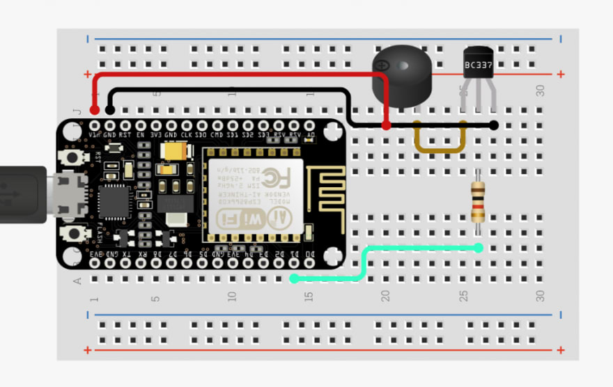 From left going clockwise: 1. ESP8266 board connected via USB, 2. connection to buzzer from VIn\
pin on ESP8266, 3. Ground connection from buzzer to GND pin on EDP8266, 4.connection to NPN BC337 Transistor from buzzer\
, 5. connection from transistor to a 1k Ohm Resistor, 6. connection from resistor to D1 pin on ESP8266.
You can also find a more in-depth guide to the circuit on circuito.io here. This will show you how to put it together in more detail. There is a code sample from circuito.io which uses the buzzer.h library to send signals to the buzzer. I am not using this for the purposes of this device. I instead will be sending signals to the D1 -- digital pin connected to the buzzer.
The Code
I'll be walking through how I wrote the code for the device so feel free to follow along. However, if you want to build the circuit and flash the code straight onto it, or even adapt my code for yourself, you can find the repo on Github.
Pre-Requisites
Before you dive into the main device sketch below, make sure you have installed the Arduino IDE and then within that, install the ESP8266-ping Arduino IDE library by within the IDE.
Add the Header Files
We will be writing this program in C so a familiarity with the language is certainly a help, but in terms of complexity, this is quite a simple program.
We need two libraries in order to make this device work. The ESP8266Wifi library will be required so that we can use your local WiFi network to contact our remote host. Secondly, the Pinger library which we installed in the IDE before we started writing our code.
In C, we add these dependencies in the form of header files referenced at the top of our code as below:
#include <ESP8266WiFi.h>
#include <Pinger.h>
Then it's time to declare our variables
const char* ssid = "your_ssid";
const char* password = "your_password";
const char* hostIP = "ip_of_host_you_are_monitoring";
#define D5 14
int SpeakerPin = 14;
Pinger pinger;
bool success = false;
Shown above, we are declaring three constants to hold the SSID of our WiFi network, the WiFi password and the the IP of the host we wish to monitor. This could be the IP of a website or a device for which you wish to receive alarms if it were to go down. You can also supply a DNS name, as the Pinger library is capable of targeting hosts by name rather than by IP.
After defining our char constants, we use the #define keyword to translate the ESP8266's pin 14 to D5, which is the digital pin we are using to send a signal to our buzzer. This means that when we set our SpeakerPin variable to the integer 14, we are really pointing to D5. This can be confusing, but we are really just accouting for a mismatch in pin assignments on the ESP8266. Take a look here for more information on how pins are mapped on the ESP8266
Finally, we have set a Pinger object, which is an instance created from the Pinger.h library responsible for the pings being sent to our monitored host, as well a boolean to track successful pings. We will use this boolean to detirmine if the alarm should sound.
Next we will make a method to connect to our WiFi network called ConnectToWiFi(), which can itself be called in the Setup() method
void connectToWiFi()
{
  Serial.print("\n\nConnecting...");

  WiFi.begin(ssid, password);
  while (WiFi.status() != WL_CONNECTED)
  {
    delay(500);
    Serial.print(".");
  }

  Serial.print("Connected to router on IP address: ");
  Serial.println(WiFi.localIP());
}
Next up, we are writing a basic method for the alarm sound. The below Alarm() method simply writes a signal to the D5 pin supply current to the buzzer (which makes it sound), waits for half a second and then stops the current to stop the buzzer before repeating the same process several times with a half-second delay between each signal change. This allows us to make the buzzer sound when we call Alarm()
void Alarm()
{

//digitalWrite() is a method that sends current to a pin which is either   HIGH (on) or LOW(off). We are sending the current to the SpeakerPin which we defined at the top of our program. (Pin D5 on the board)

  digitalWrite(SpeakerPin, HIGH);
  delay(100);
  digitalWrite(SpeakerPin, LOW);
  delay(100);
  digitalWrite(SpeakerPin, HIGH);
  delay(100);
  digitalWrite(SpeakerPin, LOW);
  delay(100);
  digitalWrite(SpeakerPin, HIGH);
  delay(100);
  digitalWrite(SpeakerPin, LOW);
  delay(100);
  digitalWrite(SpeakerPin, HIGH);
  delay(100);
  digitalWrite(SpeakerPin, LOW);

}
Next, we define the logic within our Setup() method. This is called before our program loop. In this method we use pinmode() to define our D5 pin as an output for the buzzer current. Then we call our ConnectToWifi() method and then we add an event to the Pinger object to handle what happens when the ping request has finished.
void setup() {
  // put your setup code here, to run once:
  Serial.begin(115200);
  pinMode(SpeakerPin, OUTPUT);
  connectToWiFi();

  pinger.OnEnd([](const PingerResponse& response)
  {
    if(response.TotalReceivedResponses > 0)
    {
      Serial.print("Host online\n");
      success = true;
      return true;
    }
    else
    {
      Serial.print("ERROR: Unable to reach host. Sounding alarm\n");
      success = false;
      return false;
    }

  });
}
The pinger.OnEnd event checks the ping response from the remote host and decides whether the alarm needs to be sounded. If the response is greater than 0, all is well and the success boolean we set at the top of the program is set to true, otherwise, we log an error to the serial port and set success to false. Then we can finish the program by define the method that will run continuously after Setup() is complete, Loop():
void loop() {
  // put your main code here, to run repeatedly:
  Serial.print("pinging....\n");
  pinger.Ping(hostIP);
  if(!success)
  {
    Alarm();
  }
  delay(5000);
}
Loop() is nice and simple. We are just pinging our remote host every 5 seconds. If the success variable was set to true, we do nothing, otherwise, we call the Alarm() method to sound the buzzer.
If the circuit is connected correctly and the code is without error, we have ourselves bona fide network uptime alarm! For use in production, you could put this in a small enclosure and attach a battery to it so that it will just monitor your network for you and alert you as soon as something is wrong.
Take a look at the alarm I built in this video. I configured it to monitor my main development machine. As soon as I disabled the WiFi adapter on the machine, taking it off the network, the alarm started to sound. It did not stop until the machine was back on the network.


Top comments (0)